Transmission Tunnel - Not just a simple lift and tuck
I was hoping for a nice lift and weld project, but after all weird dimensions I was fighting, I figured it would be easiest to do it one piece at a time. This allows me to check my clearnaces here and there just to make sure everything is flowing nicely. With that being said, always use shielding gas when welding sheet metal. I though my welder could do sheet metal down to 20 gauge with the regular flux-core MIG wire. But after blowing a hole in the firewall and chasing it for the next several iterations of weld-grind-weld. I finally broke down and bought a tank of Argon and 0.023" MIG wire. Oh the difference in weld quality is a thing of beauty. But like all things the more you use it the better. I think I emptied my first gas container out in about a day and a half. That's not bad from a 40 cubic foot bottle and the mount of welding I was doing.
Since I wanted alot of practice welding, and for a stronger joint, I did lap joints and welded both sides. This completely fuses the metal sheets together and there's not a "wing" to flex and break the weld. That and I was weld happy at the time. I can't believe how could it was when I was welding. There were several days where my garage was in the twenties and I'm out there sitting on the concrete floor in three layers of clothing still shivering. But keeping warm is another issue entirely.
And like always, if you mess up welding, you can always grind it off and try again.
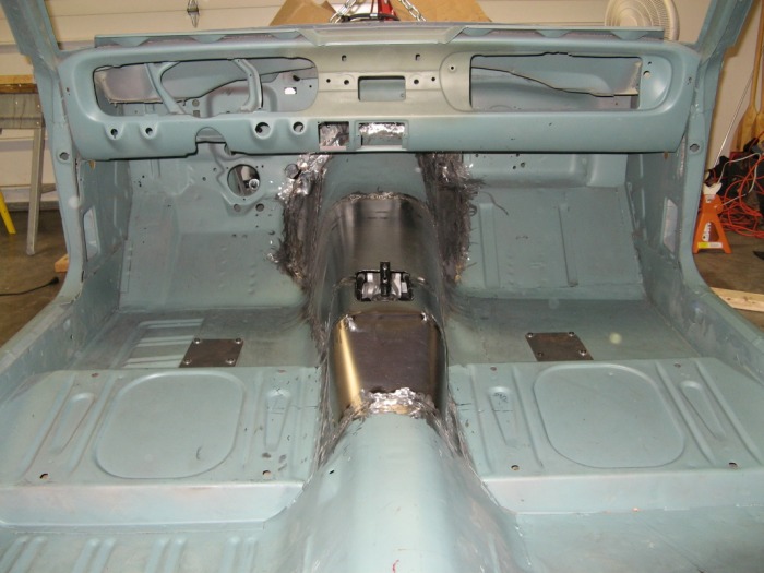
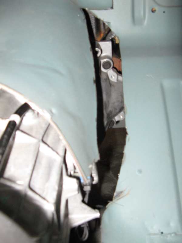
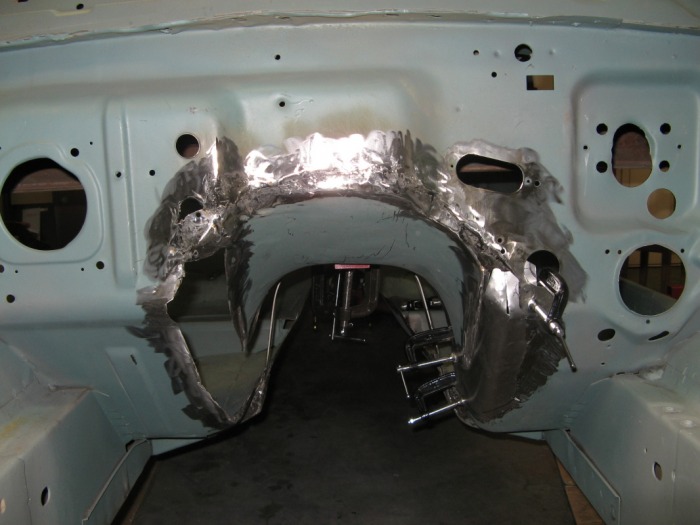
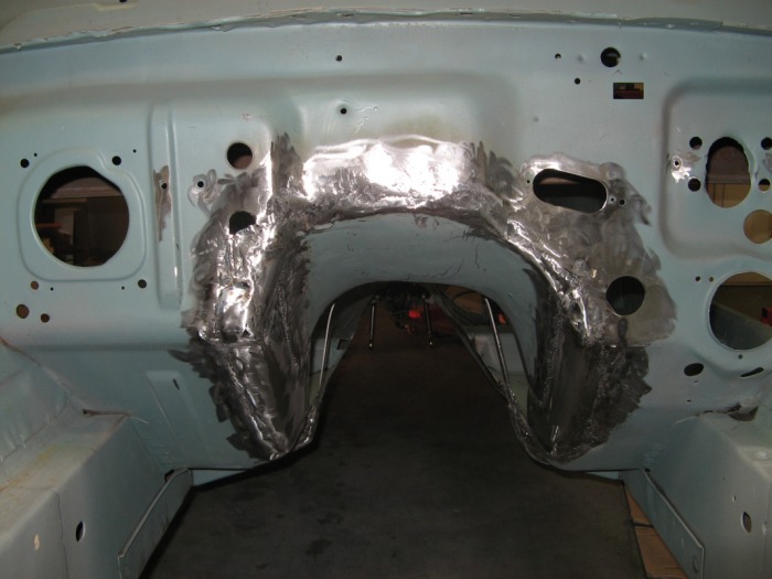
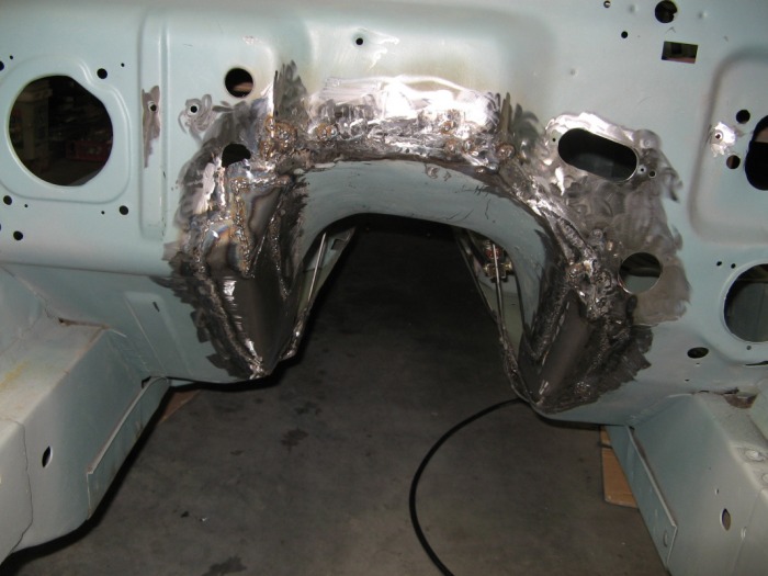
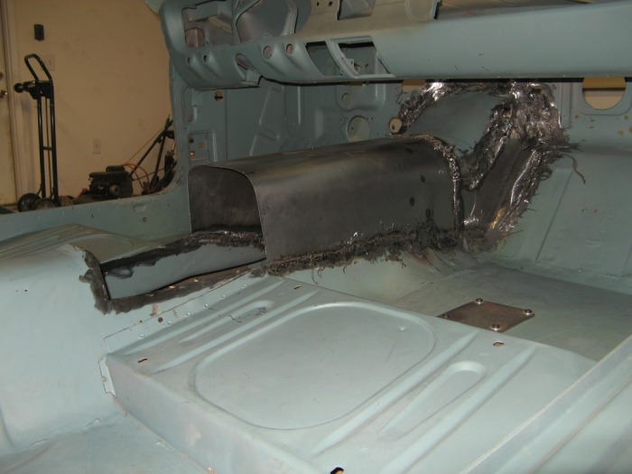
The massive hole
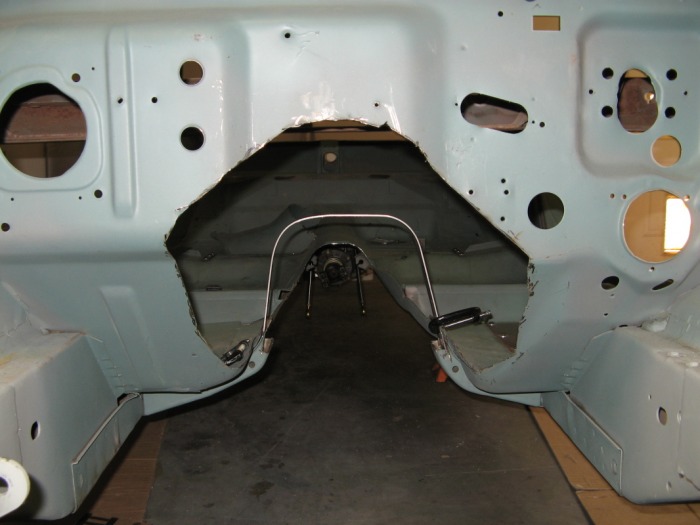
Here is the starting point for this little adventure. The first order of business wsa to figure out how high I needed the tunnel to be so that I won't have any problems with things hitting when I'm bouncing down the road.
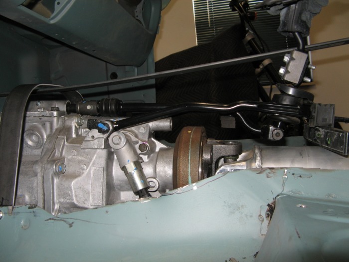
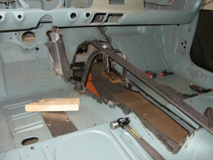
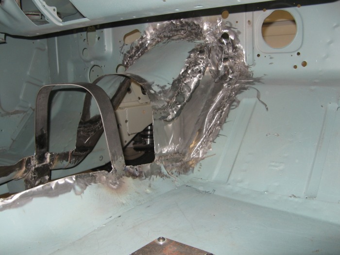
Setting the height
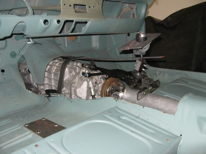
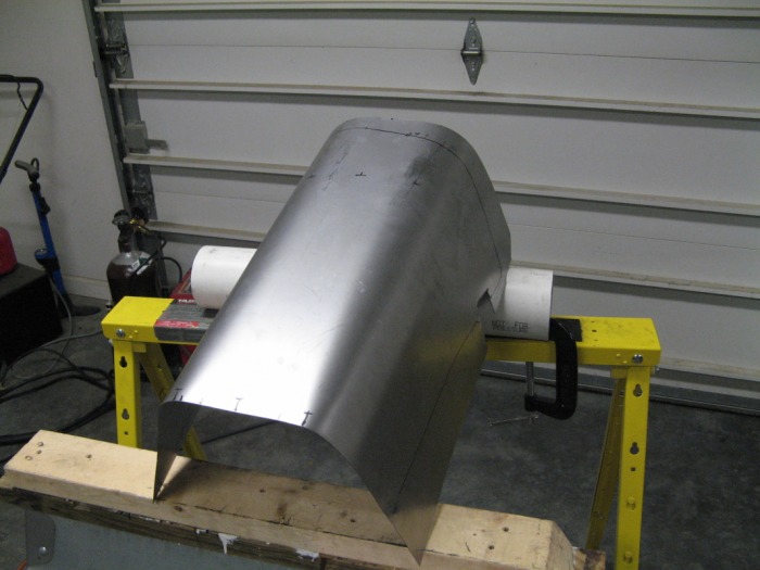
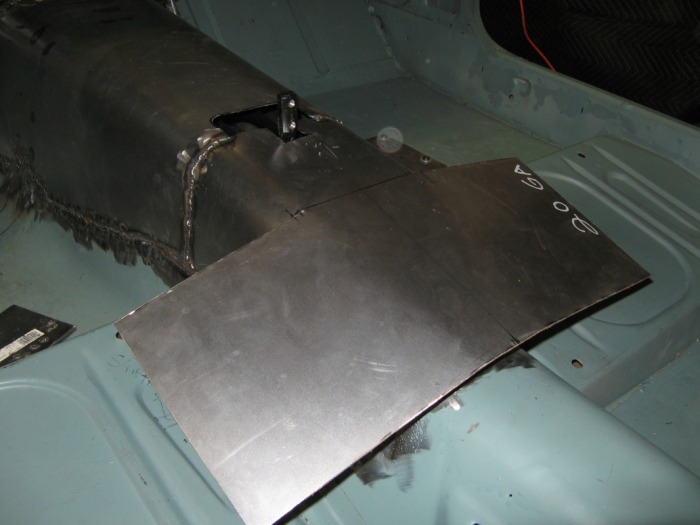
I decided to reuse the old bellhousing portion of the tunnel. Mainly because it's a super complicated curve, and it also fits all the little step-outs in the firewall for the original heater box. It actually was quite easy to slide it up and down on the firewall to get it in the right spot. But before I did that I hand-rolled a new centerlink. This is the u-shape piece over the transmission in the middle. This connects the old transmission cross brace back together. I then attached the shifter linkage and set it up so that it clears everything. I think there is about an inch or so clearance between the top of that u-piece of metal and the tranny. I then C-clamped everything in place to check how it all flows together (that's the big piece of steel that's somewhat bend in the picture.
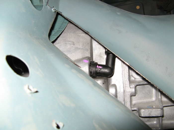
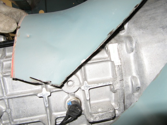
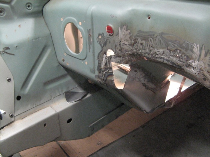
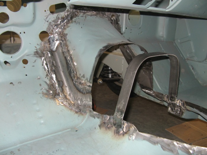
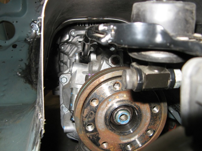
Checking the bellhousing
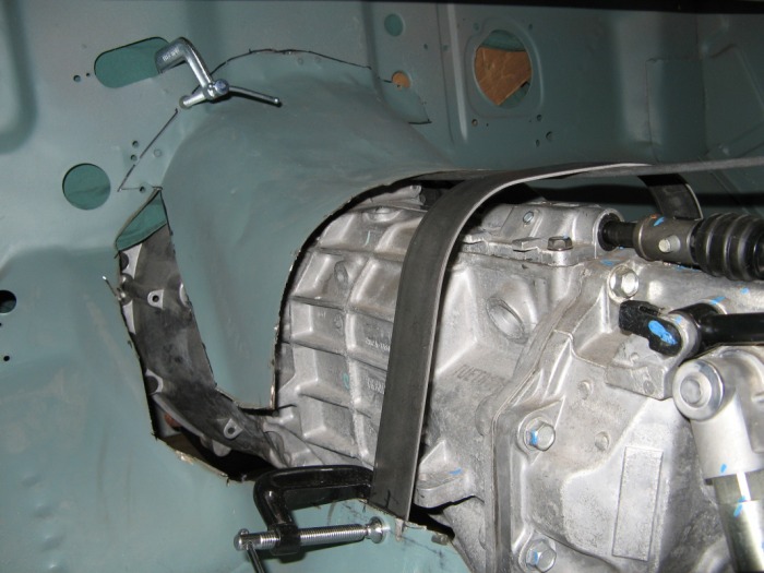
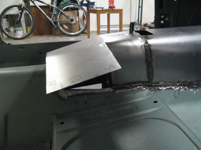
This is why I have that 3/16" piece of flat-stock applying pressure to keep the end of the bellhousing portion up. This gives me a slight slant down to that U-crossmember piece. I was surprise at how well this old piece of steel actually fit the new bellhousing on the transmission. I guess they just wanted to start playing nice together. Here is a short slideshow of the space around the bellhousing.

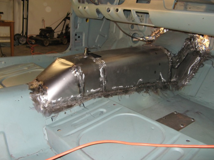
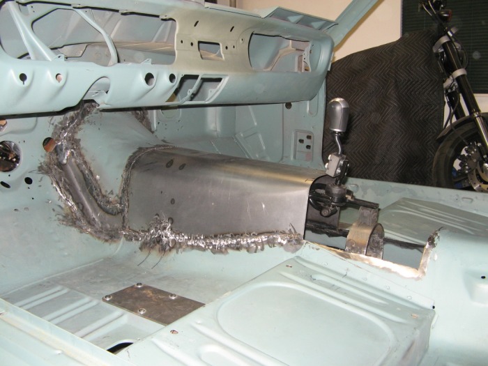
The defining brace
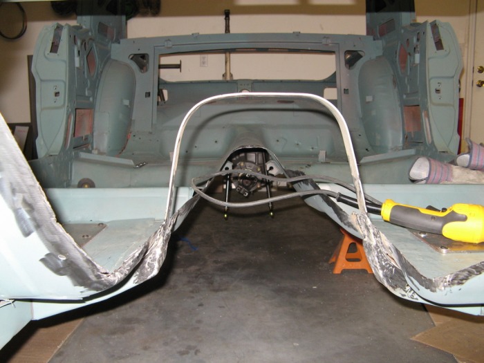
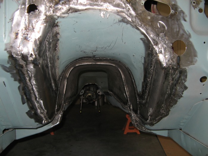
I call this the defining brace because this defines the shape of my tunnel and the height. You can see how I closed off the old crossmembers. I'm not worried about too much flex since my new suspension really does an outstanding job of trying the whole frame together. There are three main cross supports that connect the left and right frame rails together. The massive welded in front crossmember, the bolt in frame crossmember (the one I welded my transmission mount to), and a third in the rear that spans the rear axle where the pan-hard rod connects to.
Puzzle Pieces #1 and #2
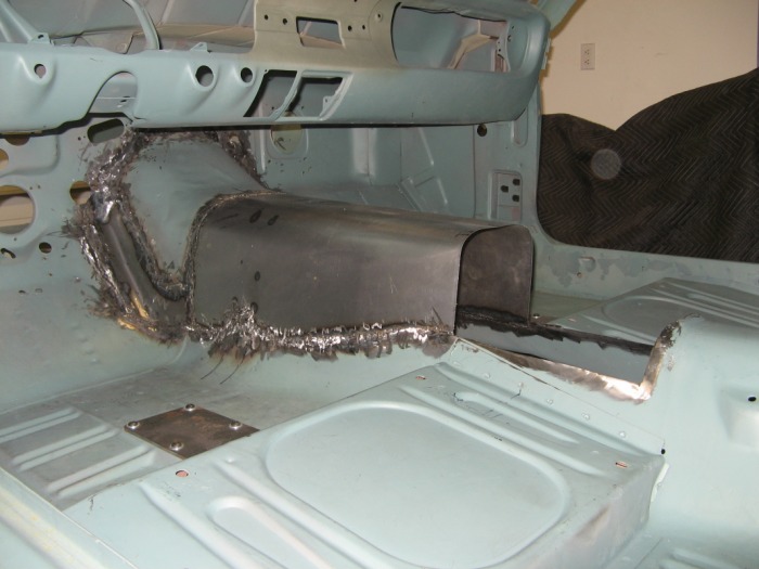
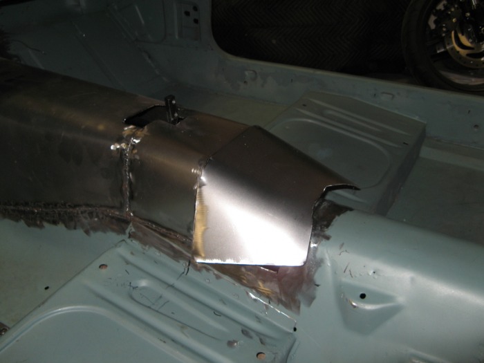
The first piece to get welded in was that bellhousing piece. You can see my marks on the firewall a few picture back. This was the first and last piece of sheet metal that I tried to weld with flux-core MIG wire. After i made a mess of the firewall, I went and bought a gas cylinder and real MIG wire. I think some later pictures show a better weld up front. Anyways, the second piece was a filler on the drivers floor. I actually just did a simple roll with a 1" piece of PVC piep to get a smooth transition from the bellhousing to the exisiting floor. I then had to cut and manually bend up the portion on the firewall. These little fillers pieces are some of the weirdest shapes. But if you start with a simple sheet and then just start cutting it done they come out pretty good.
Puzzle Pieces #3 and #4
Here I filled in the passengers floor. This piece was somewhat similar to the driver's except for the heater-box kickout. That made it very odd to do and hammer out. I actually ended up using a filler on a filler to get it right. Overall I was really impressed that I made it this far with a major screw up. Here are few candid shots to this point.
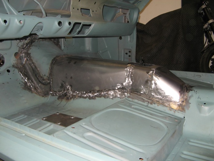
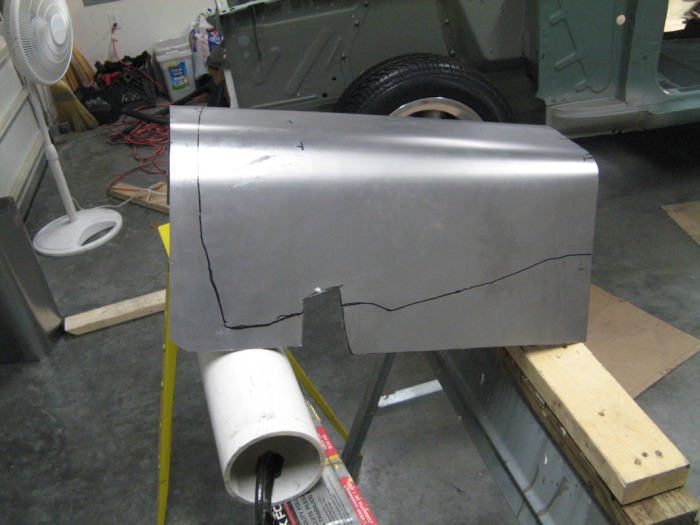
Puzzle Piece #5

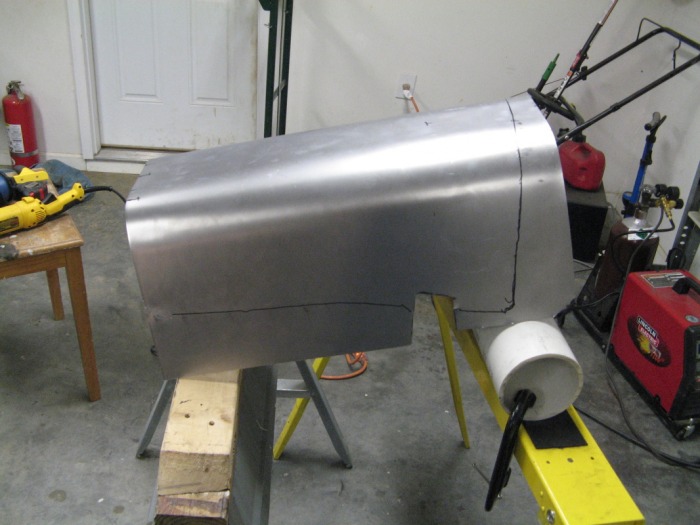
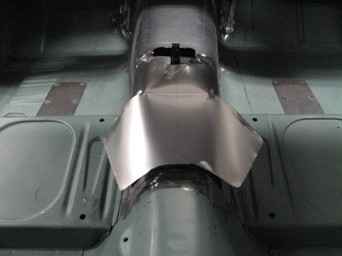
This is the main portion of the tunnel. This ends right at the edge of the seats and right where the shifter will go. Now what's interesting about this piece (besides the fact I had to make two of them because I accidentally cut too much off when I was doing my final trimming) is how I form them. I was using a piece of 3" PVC pipe from Home Depot. This gives me a really nice rolled edge. But the odd thing about this floor is that the driver side actually kicks out further than the passenger. This was to clear the old mechanical clutch linkage. But my new transmission is actually straight on the left and kicks out on the right. Either way I had to follow the floor. But this meant my two rolls weren't parrallel to each other. Oh and if you can't tell this actually slants down at 5 degrees to match my transmission angle. Here are a few pictures of how I bending these pieces up and then trimming them back to fit.
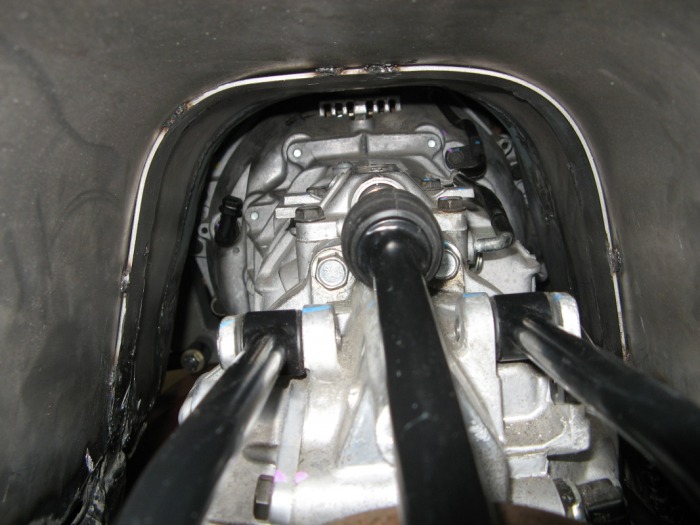
The reason to OWN an engine lift...
At this point I needed to put the engine and tranny back into their places so I can check the clearances of things. I tell you I'm getting pretty good at take thing engine in and out of the car. I there's actually only three bolts that hold the whole thing in the car. Two monster bolts for the engine and then a single bolt for the tranny and it all comes right out. Either way here are a few pictures of the clearances of things. The shifter linkage actuallys goes on pretty nicely. I lover the little pivot pins that you can take on and off with a simple screwdriver. I actually bolted this on before I jacked it up into position.
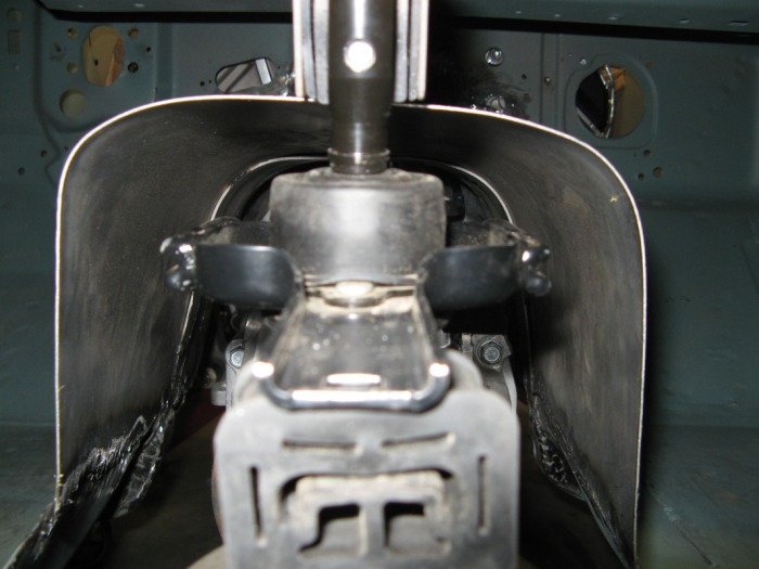
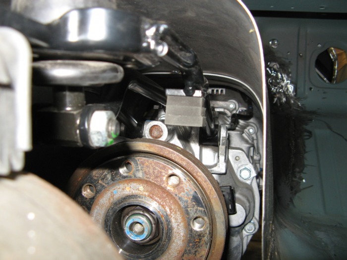
Shifter Mount
Now it's time to get that shifter where I want it. Turns out that the stock GT500 shifter linkage is the perfect length for what I was after. It places the shifter ever so nicely right about 1/2 down your thigh. This is going to be a super-fast shifting mustang now. The problem is how to get that stupid thing fixed into place. I ran around a bunch of ideas in my head, but I think the best was to use the stock rubber isolater and work from there. This allows me to replaced it with an OEM or aftermarket urethane one without me having to modify something custom again. Notice how nicely it sits right about dead-center of the driveshaft safety-loop? Keep that in mind.
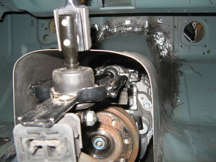
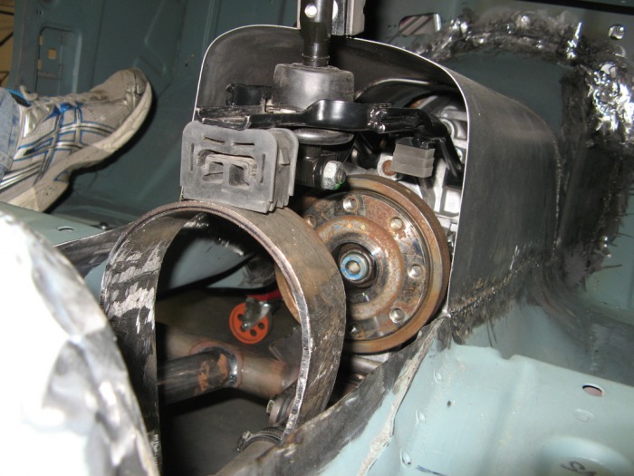
Scrap metal mount
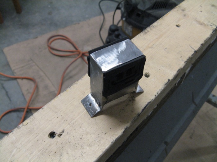
Using that rubber isolater as a guide, I bent up two U-pieces and welded them together. You can get the jist fo the main outside U-piece by the outer outline of the part. The other u-piece is actually turned 90-degrees and locks the two sides together. The rubber mount is actually squeezed in there, but is held by the little ring that is on both sides of that isolator. Now all I had to do was drill and tap two holes in the top of the driveshaft safety-loop and presto I was done.
Shifter Linkage...Done
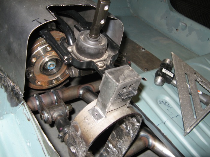
This is how everything is assembled. It's actually quite easy to do even after I finished the tunnel. You can also see where I cut out for the shifter boot. I ended up getting a nice leather boot and polished stainless steel trim ring from Lokar. I'm going for the same shifter look as what I had. I just want a nice simple, clean interior to hide anything about what lurks underneath my floor boards.
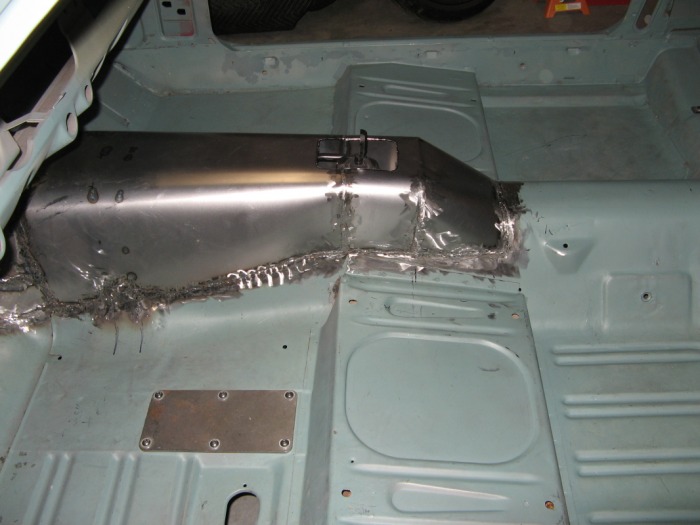
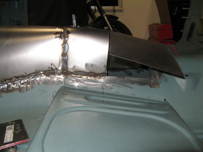
Puzzle piece #6
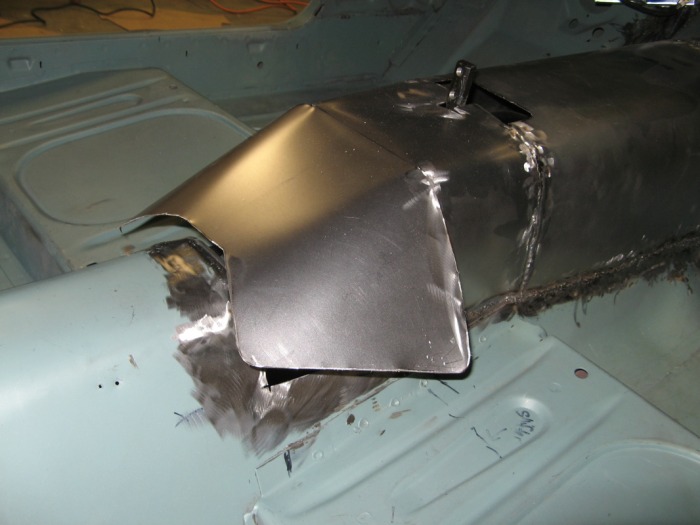
Ahh the final piece. I probably could of done this in two section. But only using one and I can get a really nice curve to finish it out. I wanted to keep the shift boot ring nice and flat, so I kept part of it flat before dropping down to finish it out at the floor. There's actually a bump in the middle of the floor there from the factory. This gave me a really nice blend in point. So I rolled and folded my last piece of metal and started fitting it in. I actually tried doing a butt-weld on the verticle seams there. They actually came out really good, not to mention it saves me 1/2 of the welding I have to do. These "wings' were actually hand rounded to blend into the car. Here's a short slideshow on how that was done:

The jigsaw is COMPLETE!!!
Yah!! Finally the floor is complete again. It took almost 3 bottles of welding gas, and alot of patience, but the final product is very nice if I say so myself. I'll probably have to get a custom piece of carpet for the front, but that's no biggie. I really like how everything tapers out into the original floor. I also love where the shifter is place now. It's going to be a joy to shift gears again. And to think that I only had to raise the tunnel about 3-1/2" to clear the transmission. Oh I almost forgot in my excitement (or since it's almost 3am on Sunday morning), here are the final pictures: