Intake - A Breath of Fresh Air
To have that long sought-after bang we must have two things, air and fuel. So the first step in that equation is getting enough quality air into the supercharger to feed the engine. This wasn't as bad as getting the transmission to fit, but it did lead to some interesting sheet metal work. Like the transmission and radiator before, the size of the air-inlet is freaking ridiculously large. Couple that with the need for a Mass Air-Flow sensor....well you get the picture another 10 pounds of crap into a 1 pound bag. Shall we?
Old Intake
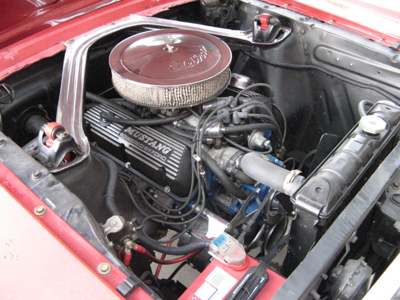
Ahh the old air filter on top of the carberator. This was done for years and years. While it was very easy to do, it did lead to alot of hot air getting sucked into the engine. Hot air is bad for producing power. Basically the colder (denser) the air is the more fuel you can efficently burn in a given cylinder stroke. Hence, more fuel equals more power as long as there is enough oxygen to get burned with it. On the same note, there were alot ways to seal off the air-filter from the engine bay, and get cold air straight to the air filter. Everything from Intake stacks, cold air pipes, to Ram-air Hoods were conceived. I think the original mustangs had some kind of air-inlet pipe that jutted out near the battery to get some fresh air. When I bought the car it had just the filter-setup like this, so that's the way she stayed. I liked it because it was a very clean look to the engine bay. But enough reminiscing, onto the problem at hand.
Everything has to be a problem
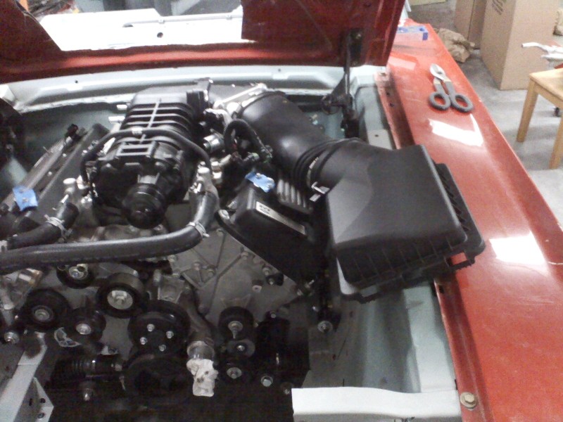
So this is how the stock GT500 intake is suppose to work. The air gets stucked in through square airfilter on the right, pass the MAF sensor, into the squashed oval inlet tube, back to the throttle body (silver thing in the middle near the rear), and finally into the supercharger. Needless to say, my engine bay is alot different from the GT500. The main difference is that I have a narrow hood and wider fenders. While the newer cars have a wide hood and narrow fenders. This gives them alot more engine room under the hood than I have. Oh well nothing a bit of metalwork can't fix.
Stock Inlet Tube

Here you can see the stock GT500 inlet tube. From what I was reading online this was really restrictive. Almost every Cold-Air intake aftermarket kit I saw replaced this with something else. Well I had it so I decided to give it a try. The main problem I had with this was those three humps near in the inlet portion kept hitting the hood frame support when I closed the hood. That and the inlet was an oval. It's alot harder to find oval pipe instead of circle pipe. So my search was on.
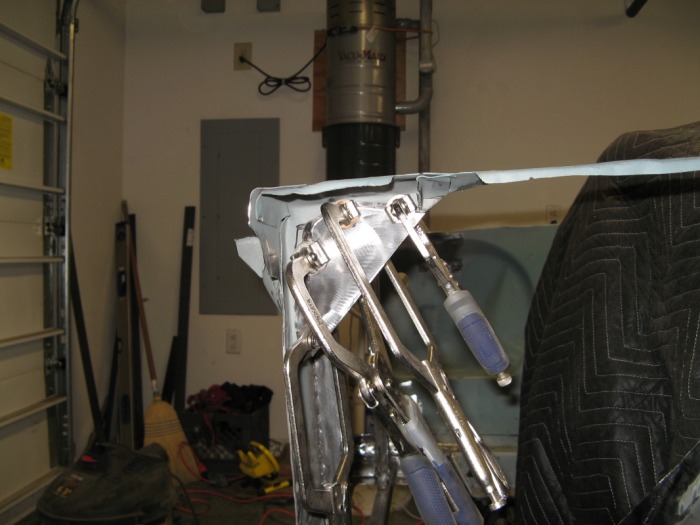
The Carbon Fiber Keystone
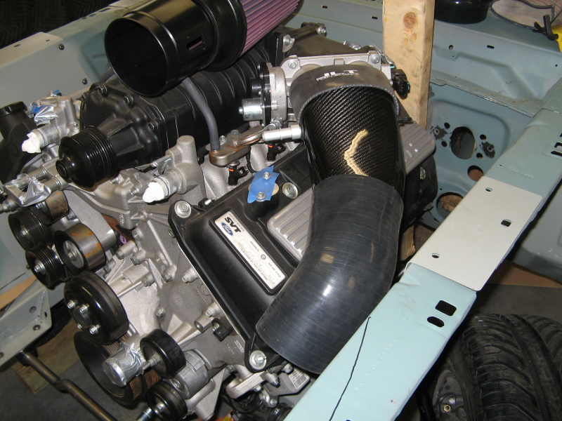
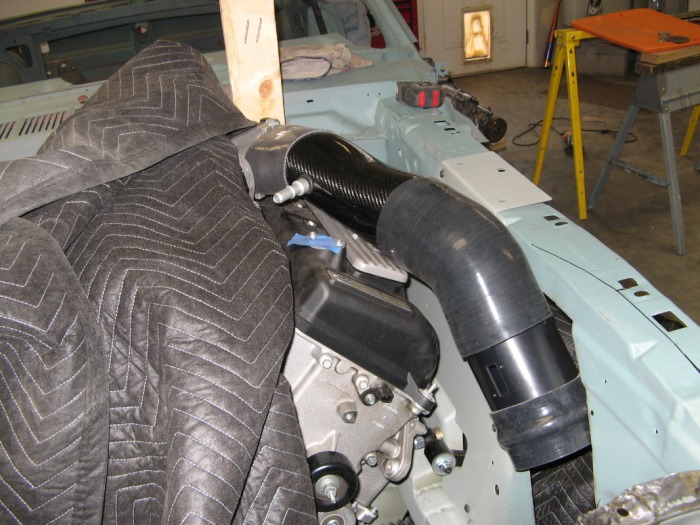
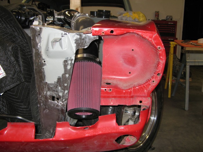
I figured the easiest way for me to make this work is to modify an aftermarket GT500 intake. So after reviewing a few different CAI I settle on this little carbon fiber beauty from JLT intakes. Here you can see the carbon fiber upper inlet tube, and part of the MAF housing and air filter (they are sitting ontop of the engine). I have a 45 degree coupler on the carbon fiber piece for testing. The main reason I chose this kit was that it took the oval throttle body open into a 4.5" OD circle which made it alot easier to find pieces to fit. That and it actually flowed really nicely underneath the hood's frame support. Here's a slideshow to show what I mean. And, YES I mounted the throttle body upside down, but that doesn't matter for the air port right now.
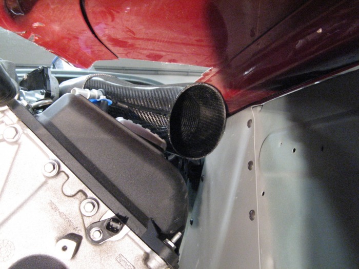
Plan 1a
If you glance back up to the last picture you can see that the inlet tube basically dives stright into the inner fender. I kept eyeing the other side of the engine bay where the battery goes, and it looks like a nice thing to mimic for an airbox on the other side. So the basic game plan is to push the inner fender out to form an airbox and then cap it on the inside to seal the air filter from the engine bay. Well that's the plan at least.
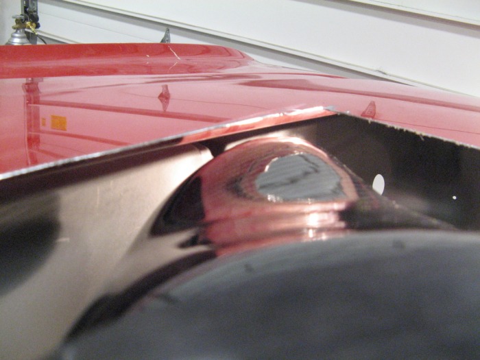
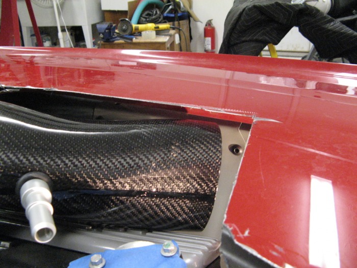
Plan 1b
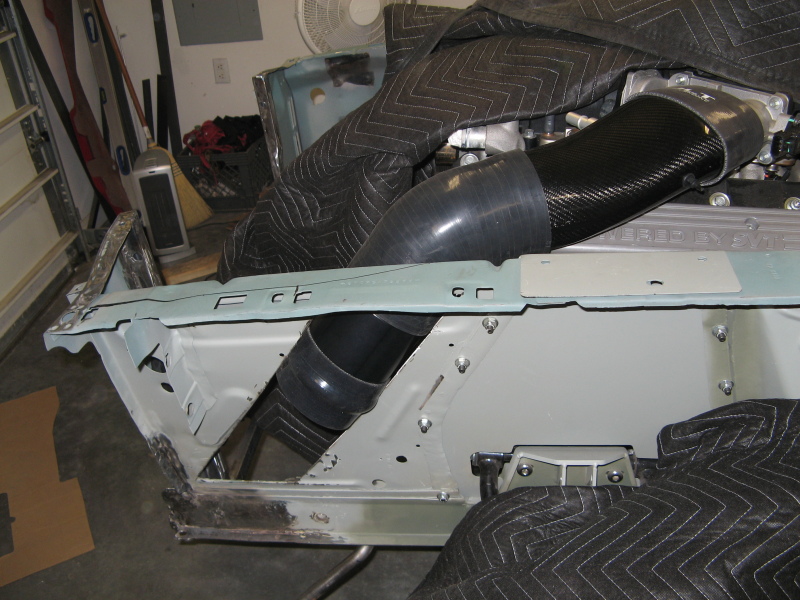
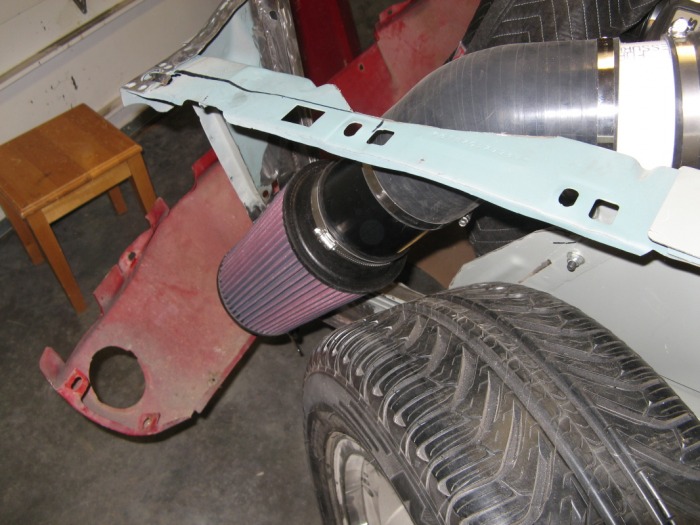
Well my older brother came up for the weekend to help me out. And he had the idea of just passing the air-inlet tube through the firewall and then have the airfilter complete on the outside. This will save alot of effort in redoing the inner fender. Sounds like a logical plan so off we went to just cut a small section out to pass the tube through. Well...sounded logical at least...
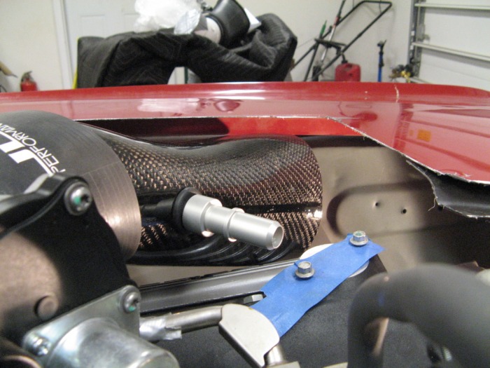
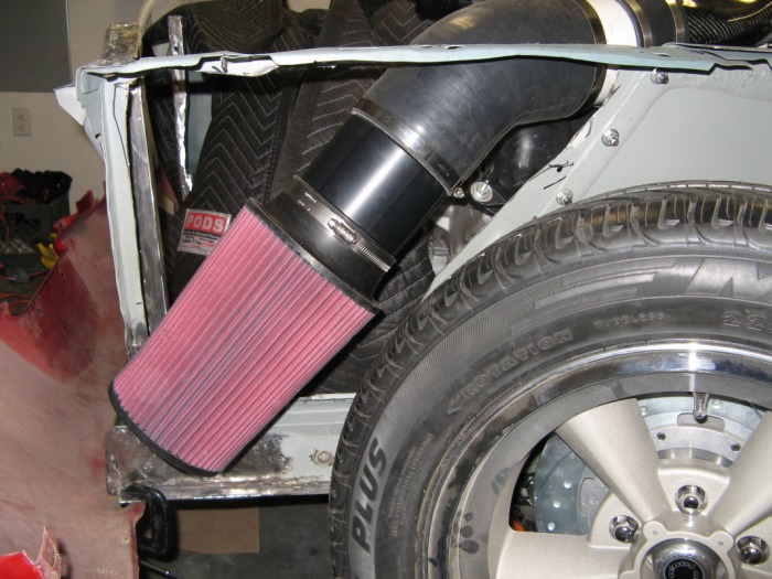
Plan 1b-#%$&!
So after testing the pipe and airfilter a bit. I got tired of fight the inner fender to get the air-filter to clear the tire. So I just cut the whole thing off and went back to the original plan.
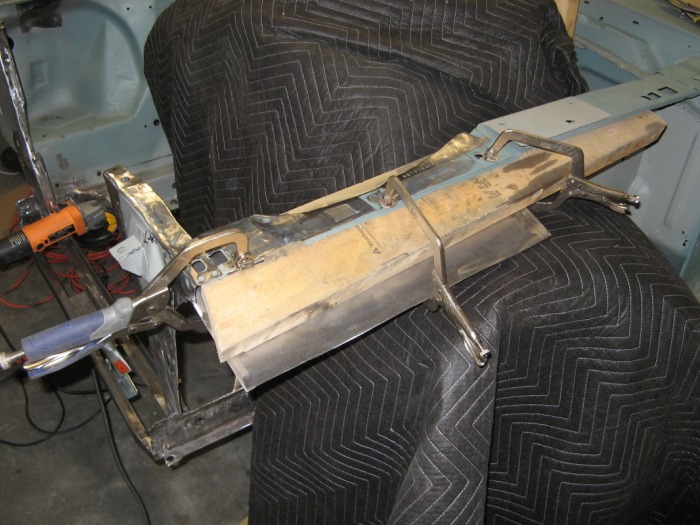
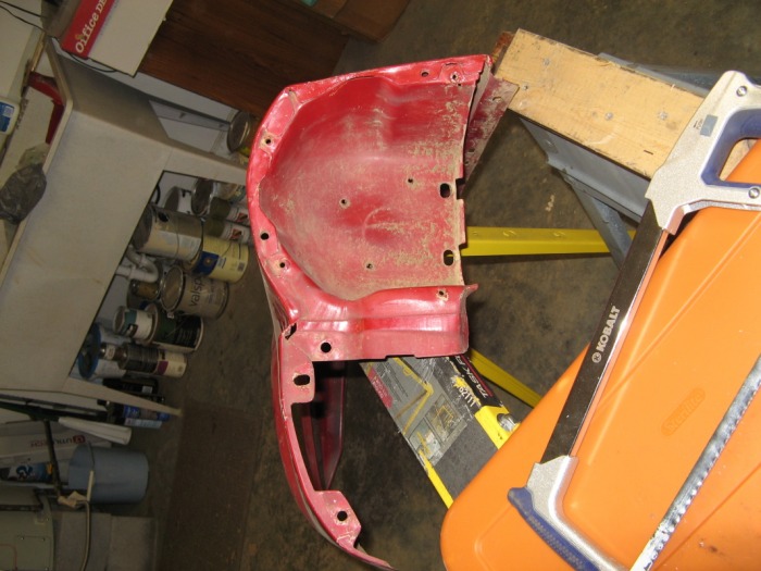
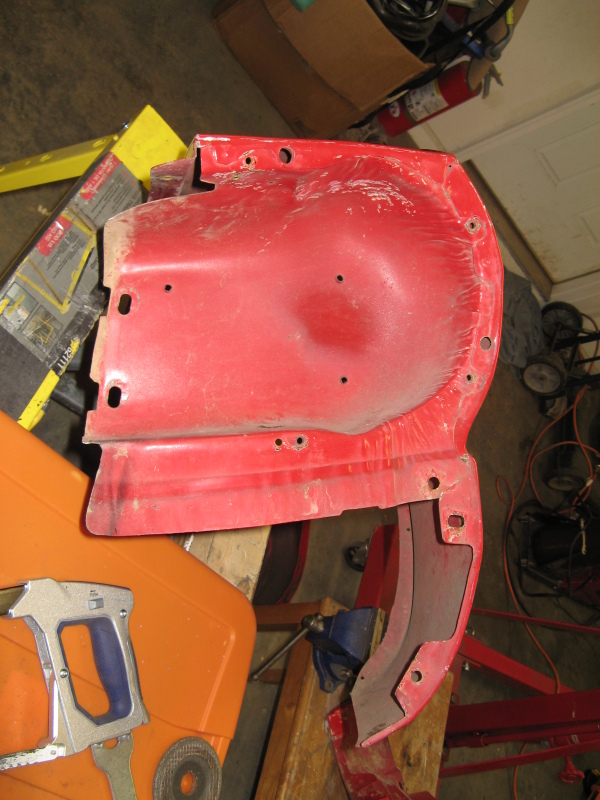
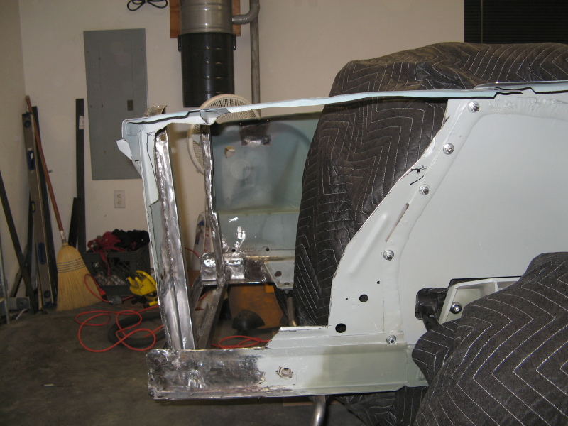
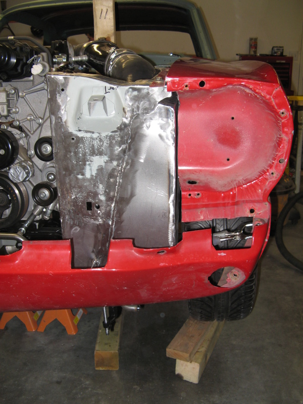
Fender Sizing

So with the inner fender gone it was time to see how much space I can really gain. Here the view of what the original front looks like. You can see on the left how much the battery box was kicked out. On the right side you can see how the fender wasn't kicked out and left flat. Well the exterior of the car looks symetrical, so I figure I could do the same on the engine bay. The first thing was making the fender look like mirror images. This allows the head-light buckets to fit the same. The following slide show shows the passenger fender, the driver fender before, and the driver fender after.
Working the top
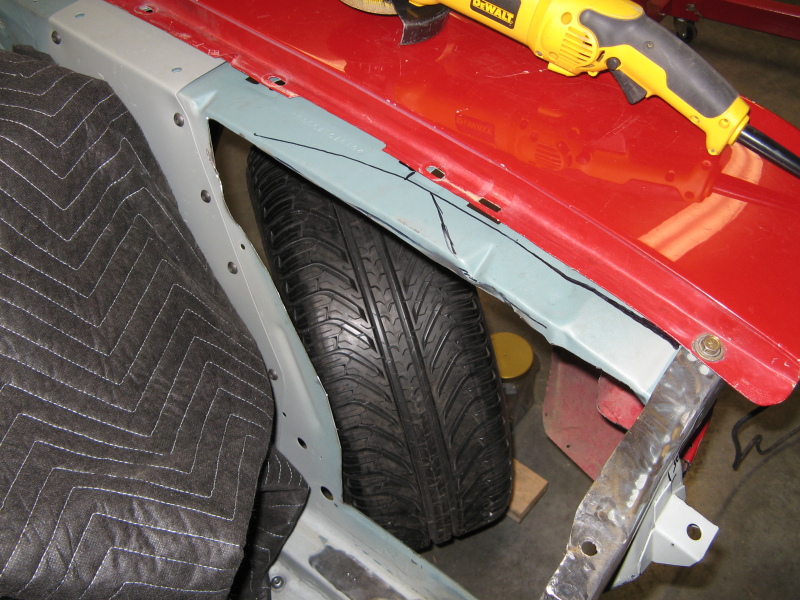
This black line mimics what the battery top looks like on the other side. You can also see the tire and the inside of the headlight bucket area too. Now remember me tell you how big this intake is? Well here a slideshow just to show you what I'm fighting right now.
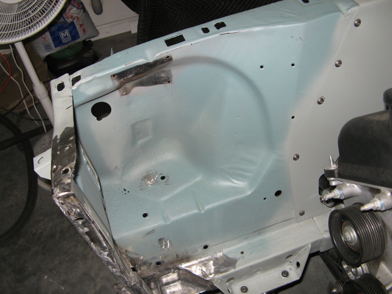
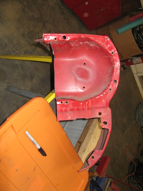
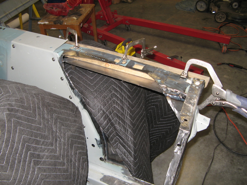
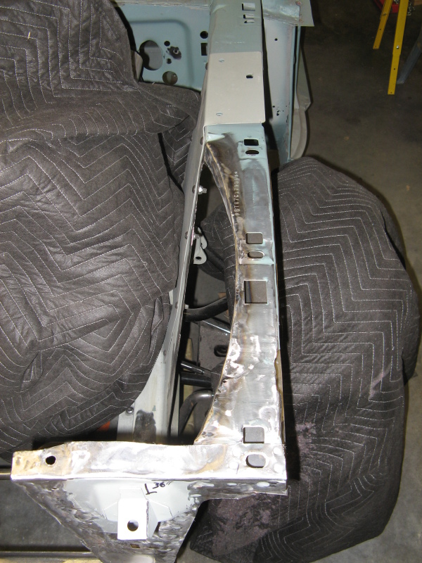
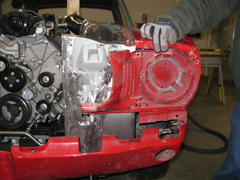
The Hole to Fill
Here's whats left of the inner fender. The idea here is to build the box out while missing the tire and leaving enough room on the top to get the fender nuts in the standard locations.
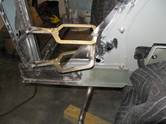
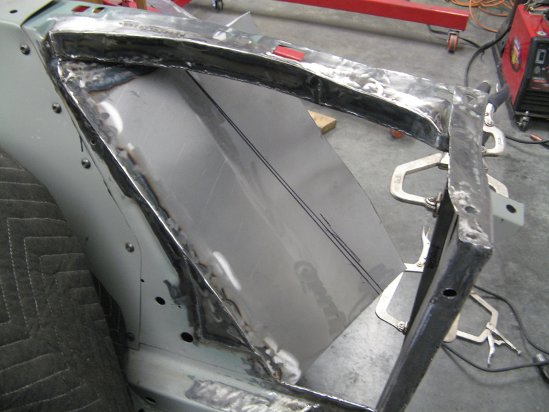
Corner Fills
I added two triangle sections here to give my airbox basic dimensions. One on the upper left and one on the lower right. I didn't know at this time but the one on the upper left is actually going to be cut out later to make it easier to pull the air filter out to clean it. But like always I welded solid and sanded smooth(ish).
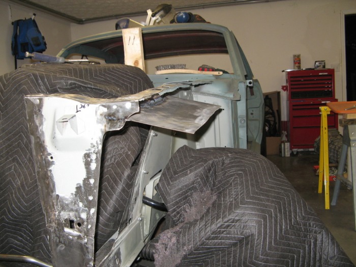
Top Angle
Just like the other side of the engine bay. There is space to get the fender nuts from the outside. This piece also forms the top of my air box. I use a 2x4 to help me angle and keep it flat to weld it in.
Top Angle - Another view
Here you can see how it angles. Since this side is exposed to the wheel. I needed to angle it down just like the other side of the car to keep water from sitting on this ledge and rusting.
Filling in the Upper Portion
Here I filled in the open space better the upper inner fender and my angle piece. Now After I did this I though the top side looked retarted so I can it out some more to finish the curve and welding in another piece to finish it off. This slidshow shows what I Mean
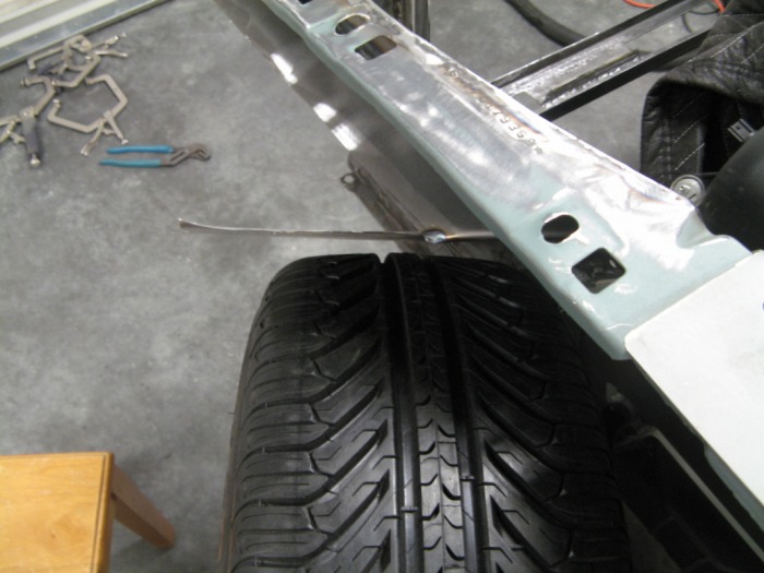
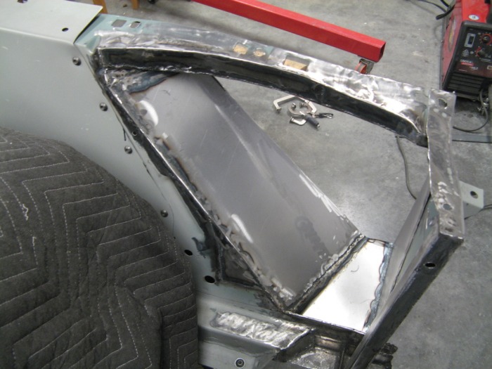
Angles and more Angles
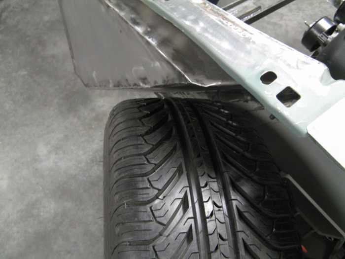
Next up was welding in the critical piece to keep the air-filter and tire playing nicely. This was set to allow the tire to clear while it was turned hard right and completely bottomed out in the suspension travel. This is equalvent to jumping off a ramp and landing only on the front left-tire while turned to the complete right. Good be prepared right?
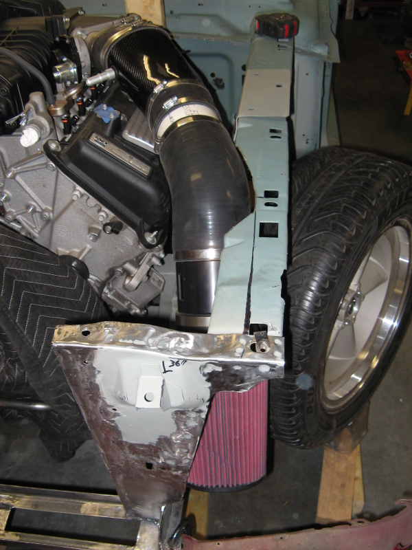
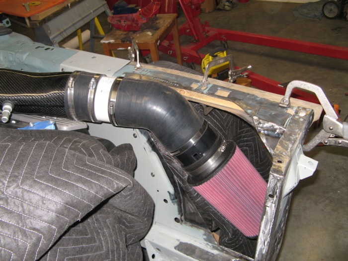
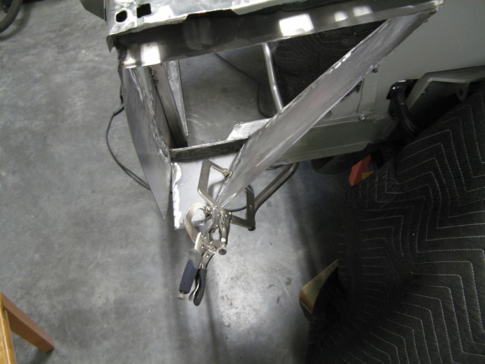
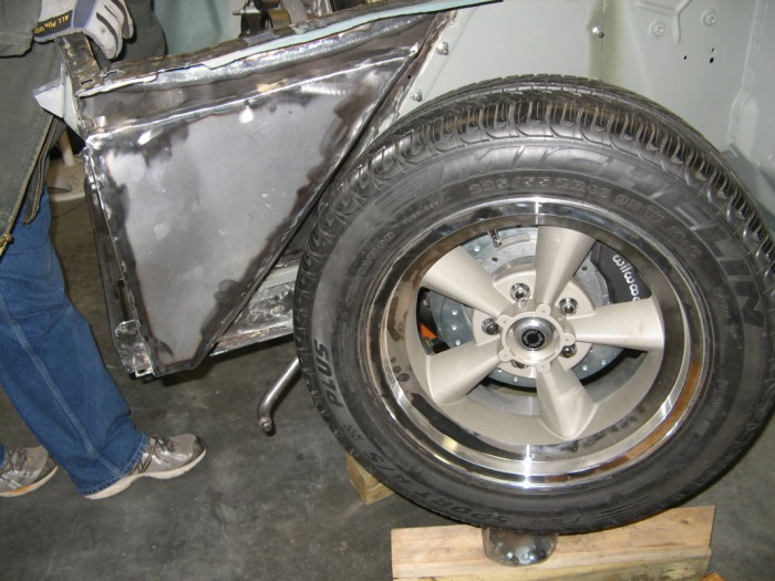
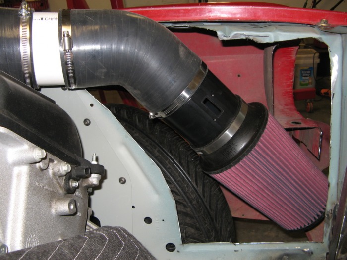
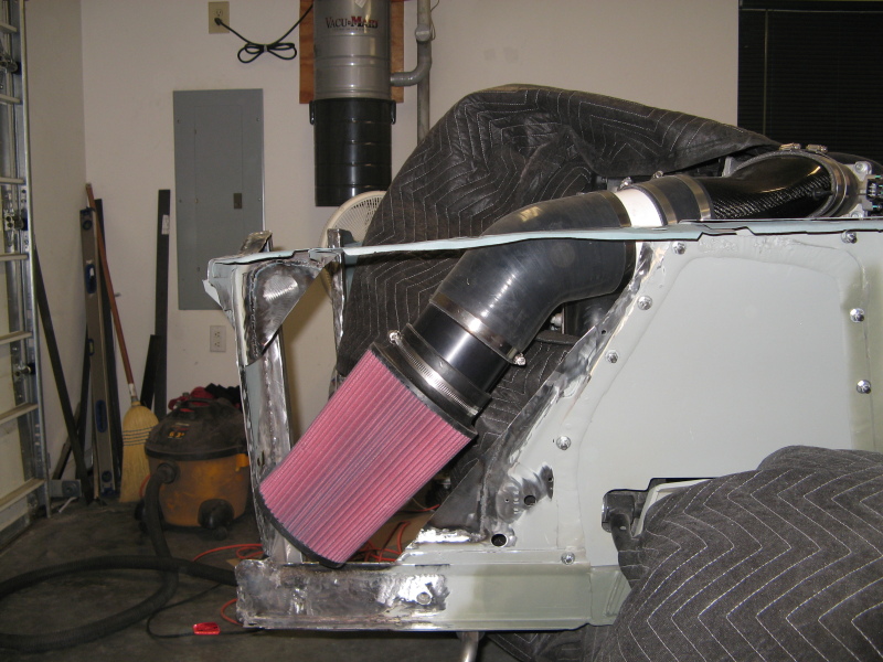
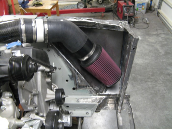
The Happy couple
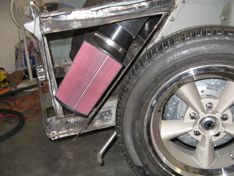
This is with the shock off the car, the tire turned hard right and propped up on some boards and a plastic nut jar. Either way the tire clears so I'm happy. The air-filter has a 45-degree bend on it after the MAF housing, but I've got a few different angles of pipe coming in so I figure go ahead and make it for the 45-degree and then I can make it move up without having to rework the sheet metal.
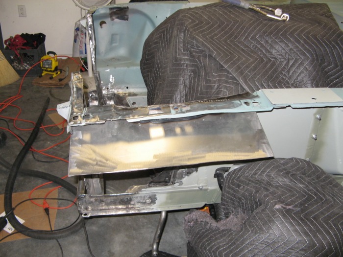
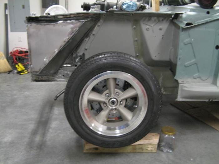
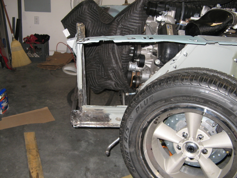
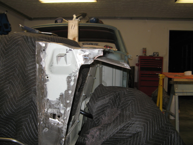
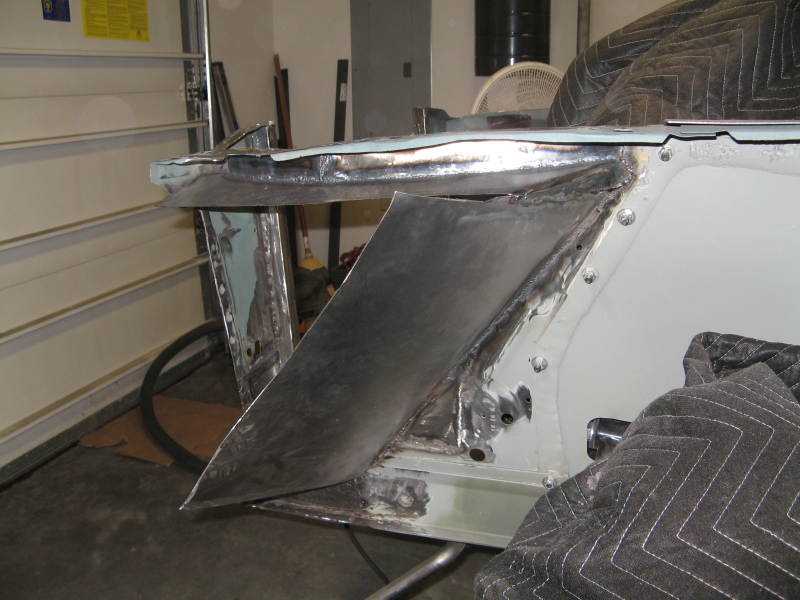
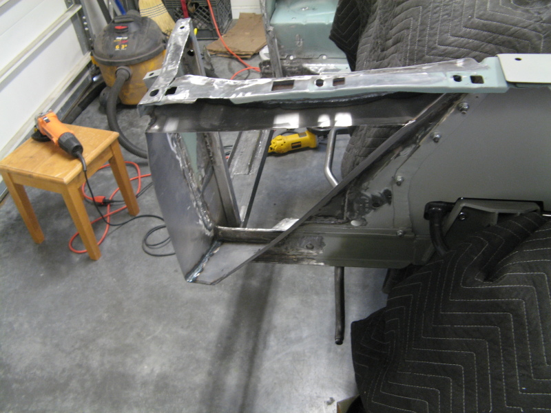
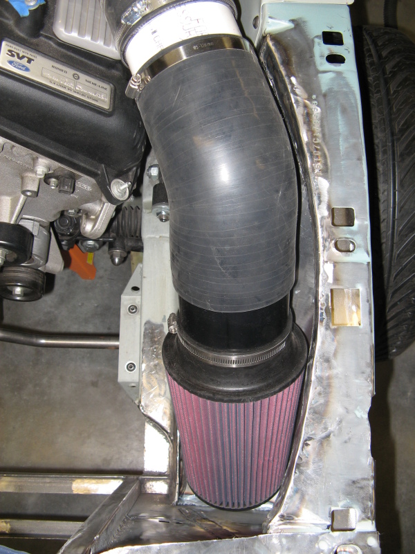
Gaining Engine Room
Here I closed off the front. You can see just how much room I gained in the engine bay by doing this. I haven't cut the rear angle piece down yet. I was waiting to get this set to see the angle I needed to cut. The outer edge of the front piece here is vertical with a level. This gave me the maximum room for the air filter that will fit next to the exterior fender. This also sets me up for the next step.
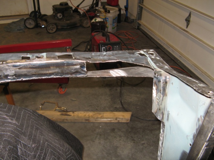
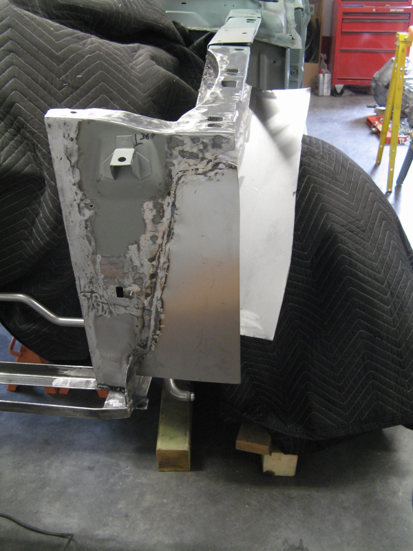
The Odd angle
This was a interesting angle to cut. Basically I knew the front and rear sections meet at the top straight with the outside of the car. This was easy to mark by the top angle piece I welded on a while back. The bottom point I had to clamp some square tubing on to keep the front piece straight (you can see this in the picture). then I look a speed-square and held it perpendicular to the front and just let it touch the back piece at the bottom. This gave me a point on the bottom that is on the same verticle plane as the top angle. Then I ran a line across a straight edge to give me a line to cut on. Oh and the reason there are two lines. The inner line is was made without moving the rear panel. The outside line is made with pulling the rear panel edge a bit forward to give the tire a bit more cleanarce. Confused yet? Basically this is how to make sure I have a flat outside piece.
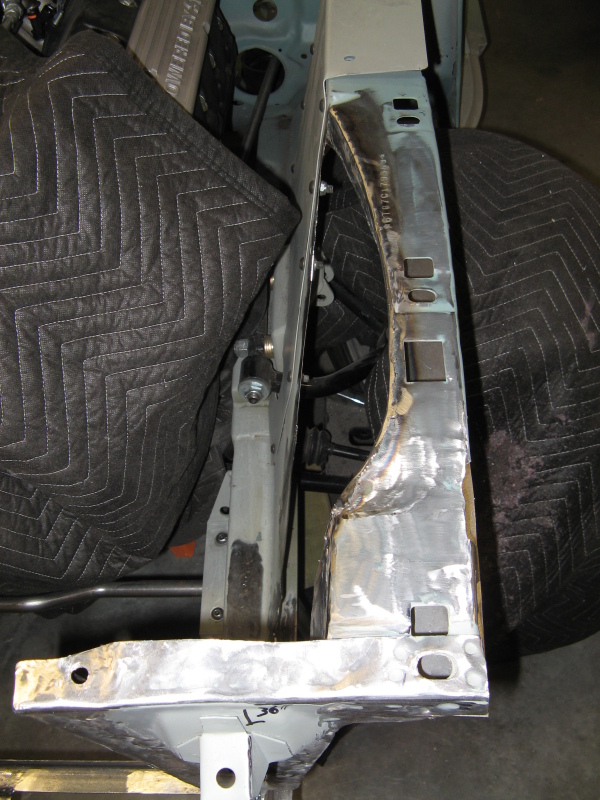
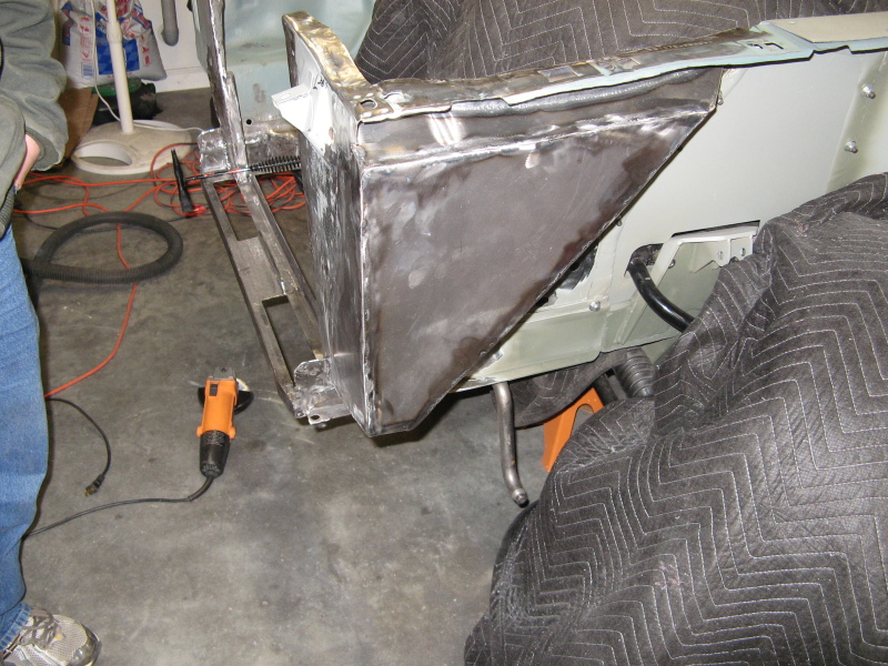
Filling in the bottom
With the rear angle piece cut I can now fill in the bottom. This was a tricky piece because I had to match the angle of the frame rail and the angle of the rear piece. After a bit of trimming with some shears I finally got it to fit right. This piece also angles up a bit to help the water run off a bit. I was thinking about setting this the same height as the frame rail to get a smooth edge, but it cut too much off the air box and won't allow enough are to the rear side of the air-filter. So I positioned it a bit lower and left the frame rail.
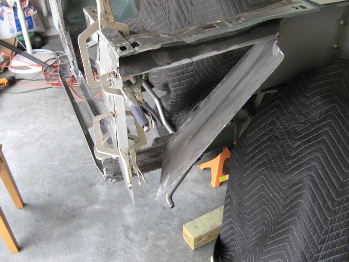
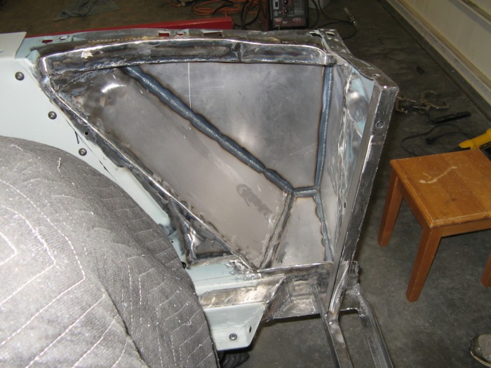
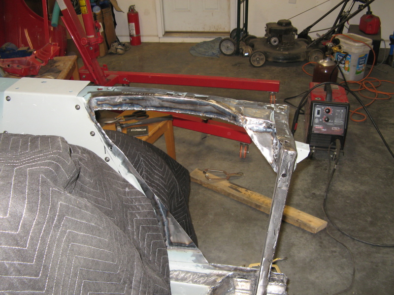
The Final Piece of Triforce
If you got the Zelda reference there good for you. If not, you need to play some more video games. Anyways, here's the last piece cut and welded on to finally close off the air-filter from the outside elements under the wheel-well. There was alot of welding on this section, but it looks really good. Jeremy came over about this time, so I let him do the touch up welding. But now for the final clearance checks. Here's a slide show of some of the clearances
But What of the Fresh Air?
I'm thinking two things. 1- The opening for the grill sits right dead on the upper portion of the air-filter. 2- The Shelby lower valance has brake cooling ducts that sit right dead on the bottom portion of the air-filter. Either way, I might open both sections up to get all that high-pressure air of the front of the car rammed straight into the air filter. I haven't made the final cuts because I want to get my final inlet pipe to see where exact the filter is going to be. I also have to figure out how to keep the rain/water from getting sprayed into the air-box with the rest of the good stuff. But at least I can work on something else for a bit. And like always, here are a bunch more random pictures of this little mini-project.