Brakes (noun): The inverse of the go-go pedal
Well coupled with a high-performance engine you have to put high-performance brakes. So I opted for disc brakes at all the wheels with larger than average rotors. I also wanted fixed calipers at all the corners since they were alot easier to work with and you don't have any parasitic clamping force losses due to floating calipers. TCI offer a couple of different setups fom Wilwood but I opted for the 12.25" rotors with 4-piston calipers. This allows me to keep a nicer 16" wheel on the car because the 17" wheels just look kinda funny on older mustangs (my preference). These Dynalite series of calipers also offer stainless steel pistons verses aluminum ones on their higher end sets. I know they are probably perfectly safe, but I trust stainless steel pistons in corrosion prevention over aluminum pistons any day of the week. I'm going to show this page how the fluid flow from the brake reservoir to the calipers.
Brake Fluid Reservoir
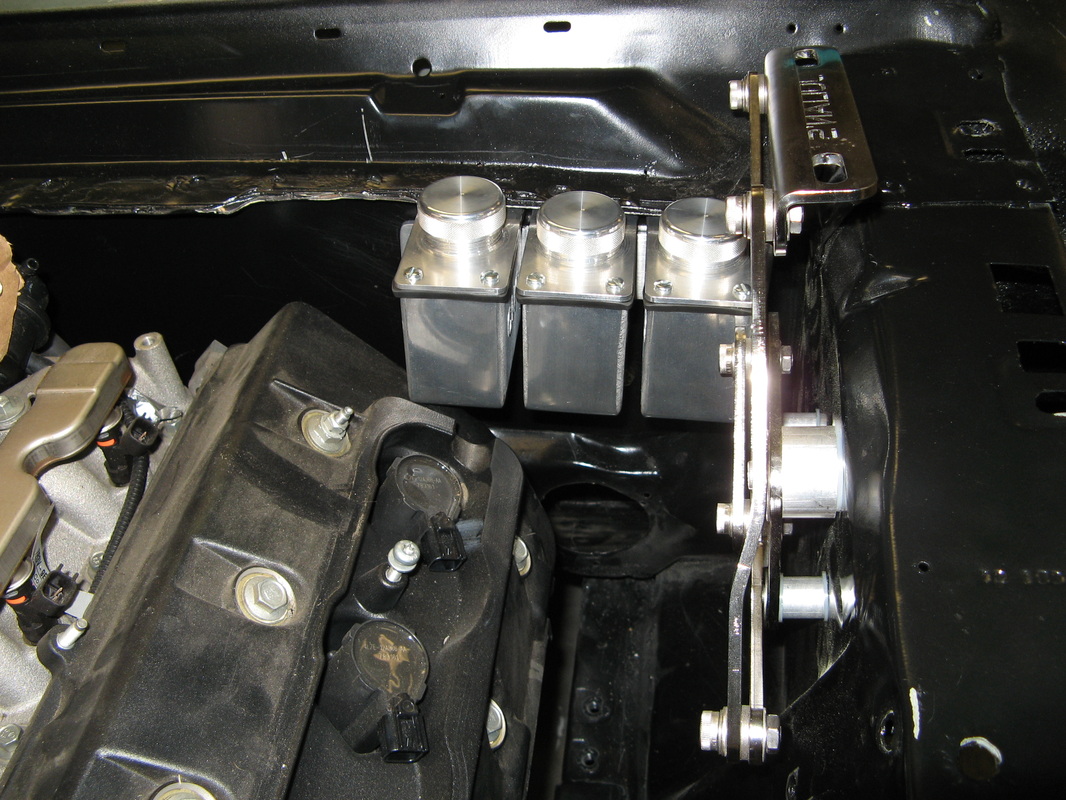
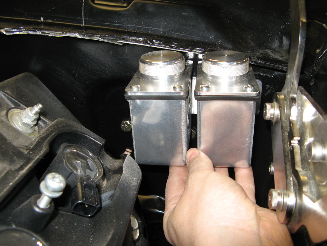
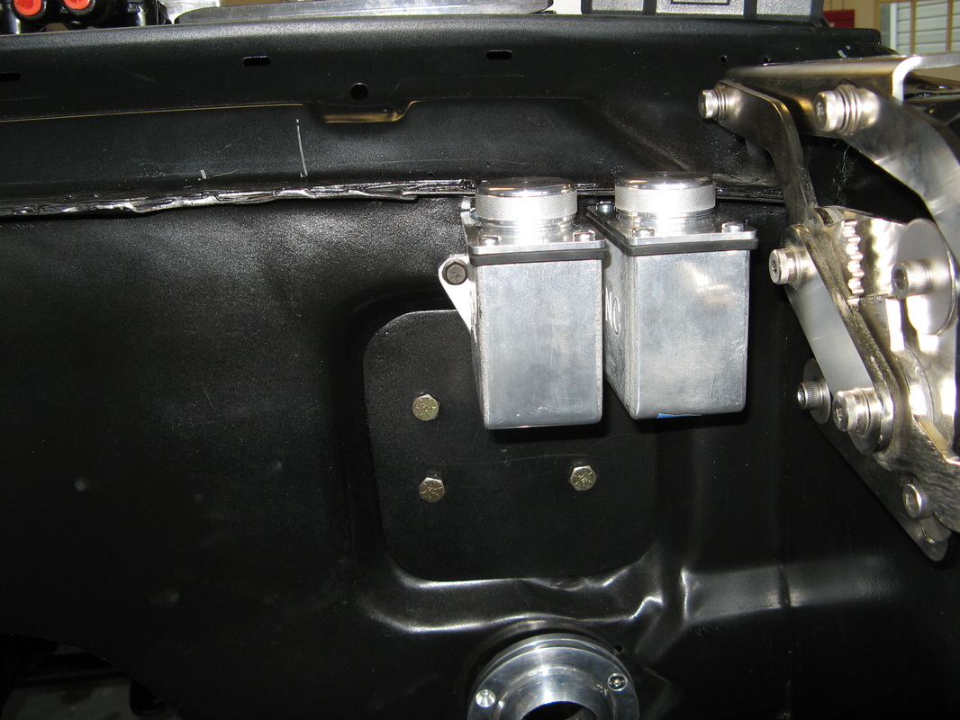
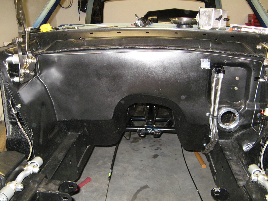
This is the container in the engine that keeps the brake fluid nice and clean and ready to go out to the master cylinder and beyond. Usually this is mounted directly on top of the master cylinder, but since my master cylinder is located inside of the dash these become remote reservoirs. I originally was going to go for a different reservoir for each the front and rear brakes and the clutch, but after dropping in the engine again, I decided that it would be better to go with a single reservoir for the brakes and one for the clutch since three of these chambers just wouldn't fit right. I might try just having these two large reservoirs for the brakes and then place a smaller one for the clutch. But I'll have to look again once I get all the hoses and electrical trimmed out on the engine. Anyways, here are a few pictures of why a triple setup wouldn't work and what I actually ended up with.
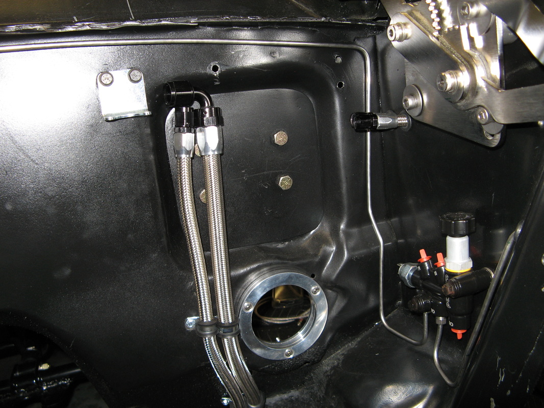
Brake Reservoir to Master Cylinder Hoses
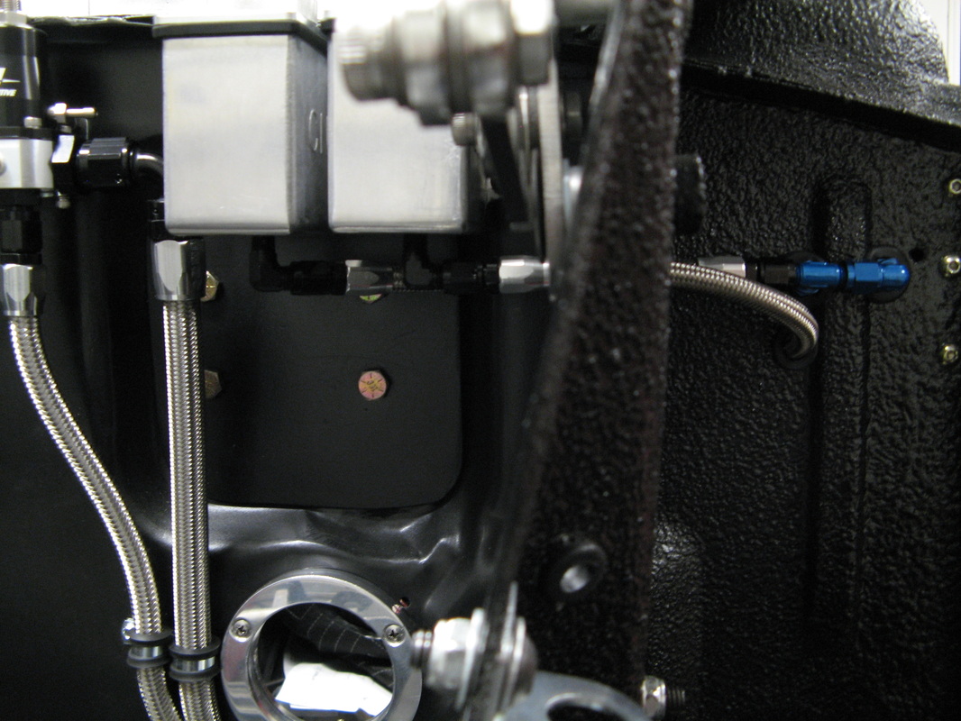
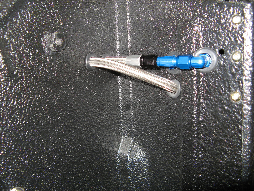
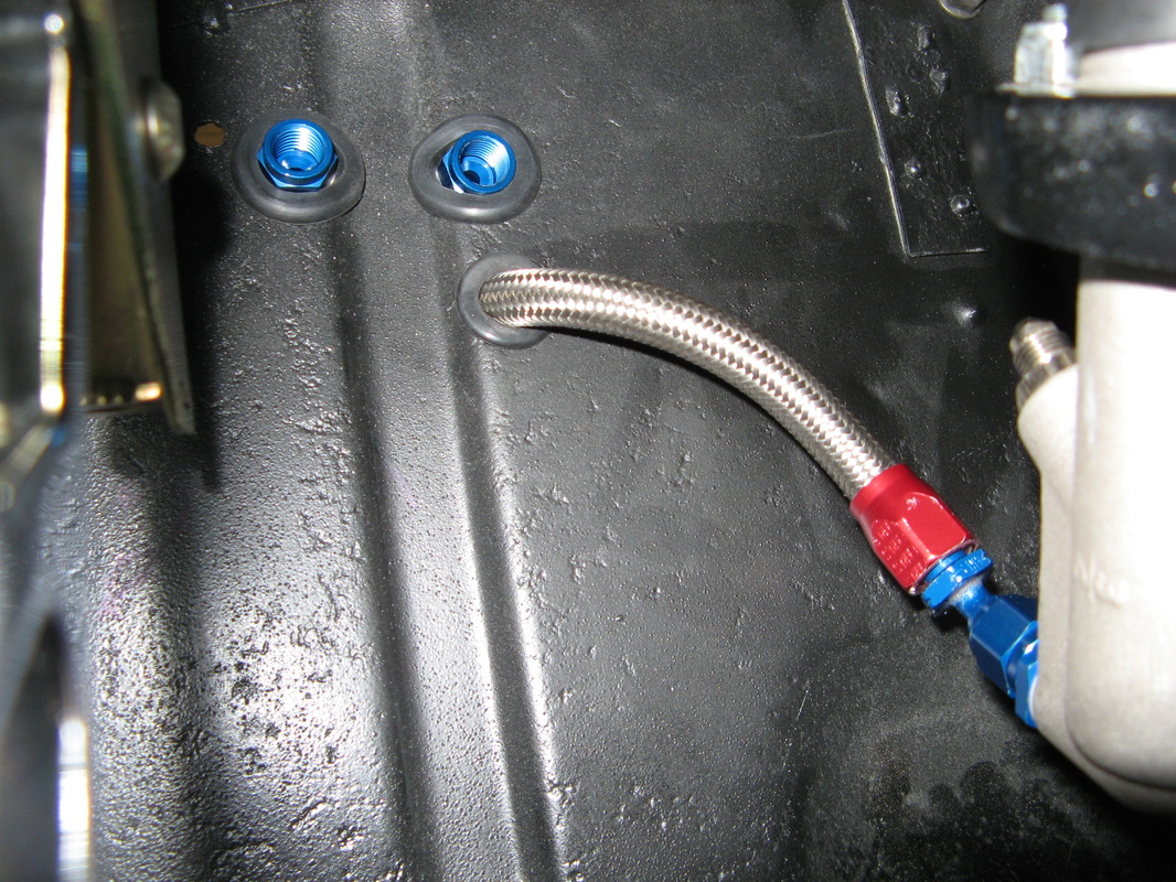
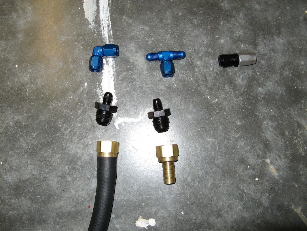
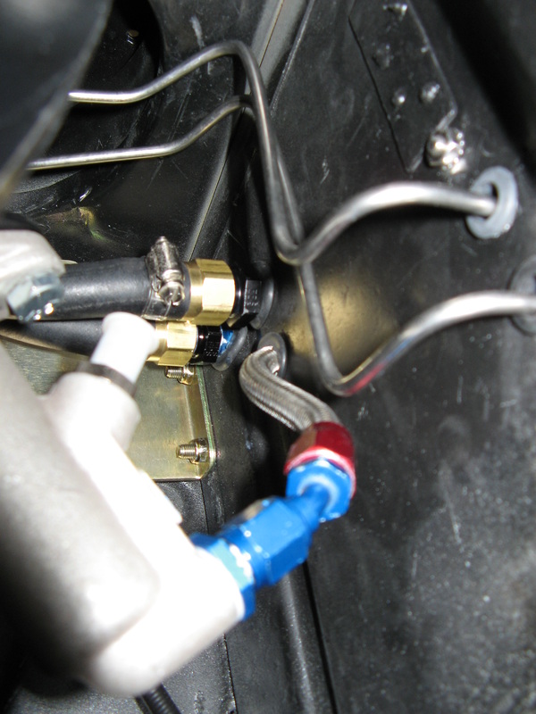
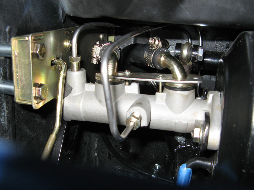
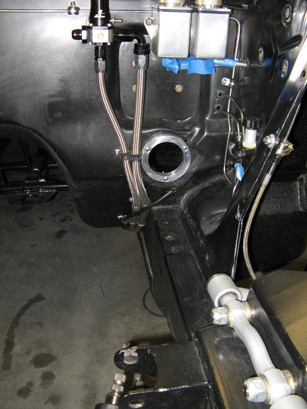
Here was an interesting little setup. I had to run a hose setup that would connect a 1/8" NPT hole on the reservoir to two 1/2" hose barbs on the master cylinder, all the while remembering that this was a gravity fed system. Well after finding some interesting adapters, I ended up with a single -4AN hose run that T'ed off at the firewall to two 1/2" hose barbs. It actually came out pretty nice once all was said and done. Here are a few pictures to see the run.

The Master Cylinder/Brake Booster
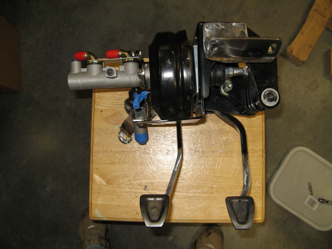
Like you've probably seen many times before, here is the master cylinder and brake booster for my car. So to spare the you ramblings of other pages, I'll keep it short and simple. The Brake booster is the large black cylinder in the middle. This uses engine vacuum to create a negative pressure chamber behind a large diaphram. When you apply the brakes, the ambient air is allow to press down on the front side of this diaphram (which is at a higher air pressure than the backside) giving you alot of extra pushing power to press the master cylinder pushrod. Hence the term power assisted brake booster. Now this pushrod presses fluid out of the master cylinder and down to the brake cylinders which in turn clamp the brake rotor bringing the vehicle to a stop.
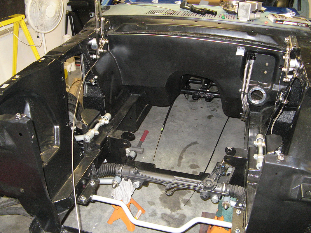
Master Cylinder to Proportional Valve
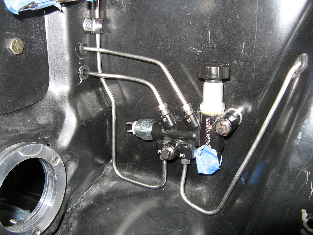
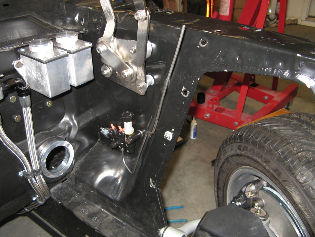
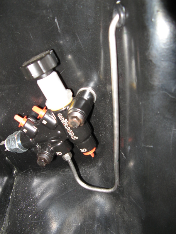
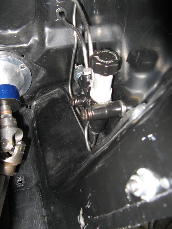
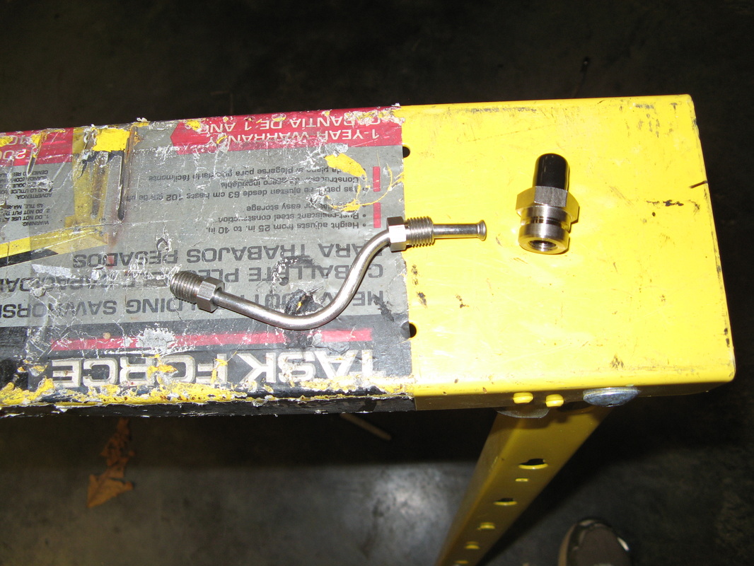
Before I get into this section I have to say that if you are going to run custom stainless steel brake lines, get yourself a Ridgid tubing bender and double flaring kit, and a Imperil inner/outer tubing reamer. I can't believe how nice these tools are for making painless double flares and very nice looking brake lines. Anyways, for this run I was actually thinking of breaking these into two lines to get them through the firewall, but I found a very neat little path that dodged the clutch pedal, so it was a straight shot to the proportional valve. Speaking of, this Wilwood proportional valve was a pretty neat little setup. It contained the splitter for the front brakes, the proportional valve for the rear, and even an integrated brake switch. All I can say it I'm so glad they shoved all those little bits and pieces together. It makes my job routing lines alot easier.

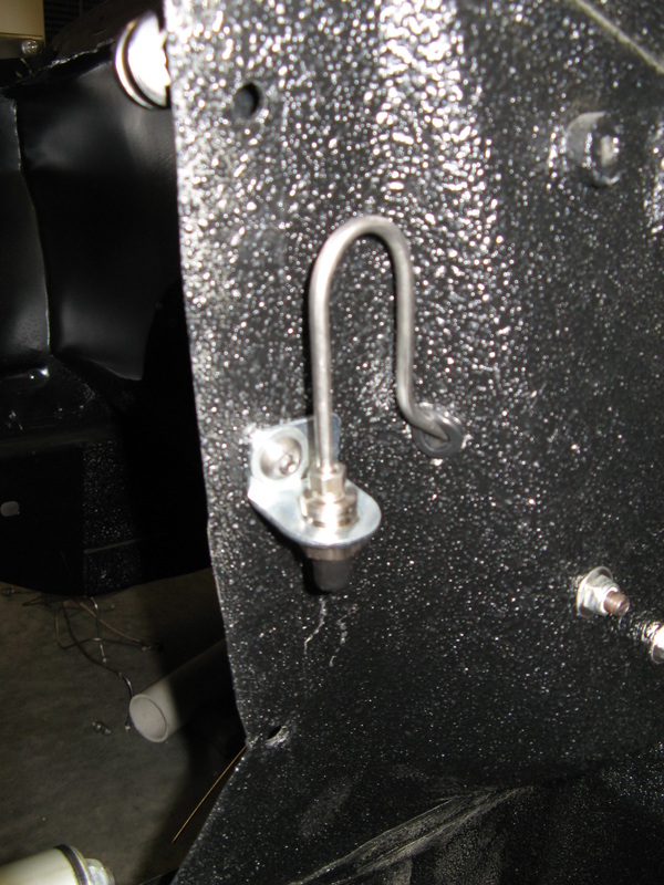
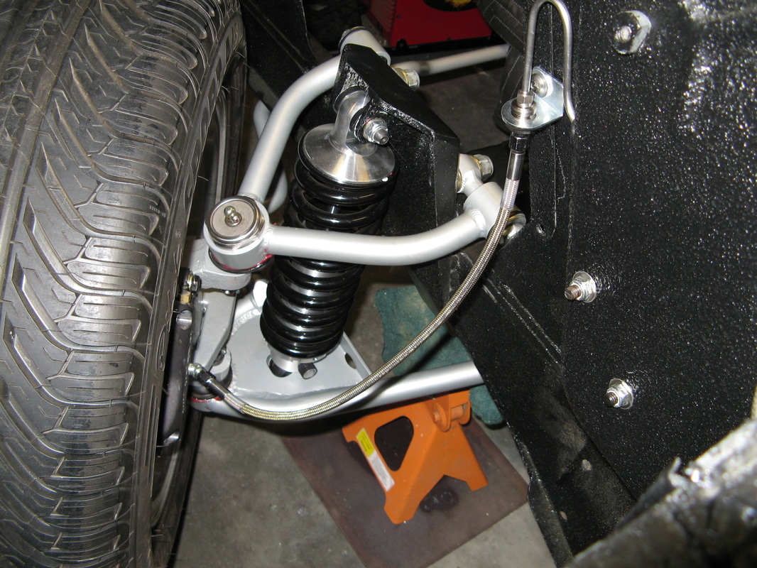
Front Left Brake Line
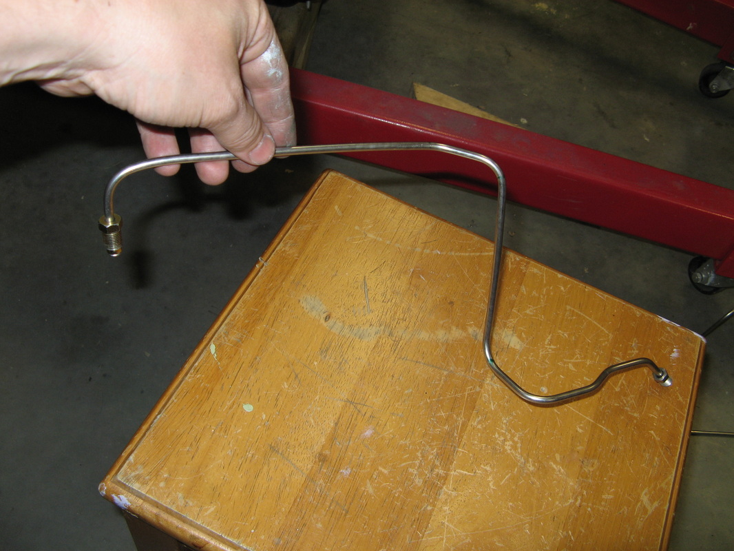
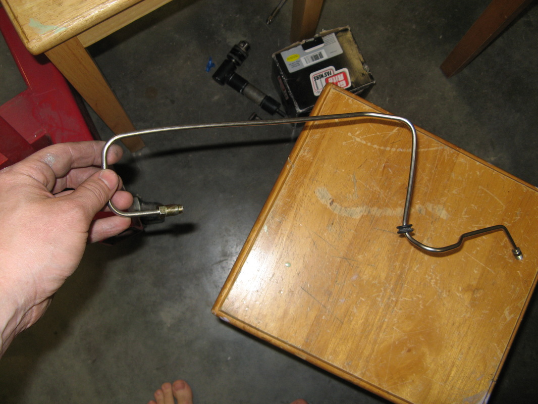
This was actually my first brake line I bent up. I did a few test bends on some scrap pieces with my new bend to get used to it. My old bender sucked and actually broke the last time I used it, hence buy some quality tools to do brake lines with. Anyways, here are a few pictures to show how I was figuring out how to place each bend to get it to dive through the inner fender panel and into the flex line for the brake caliper. I might go back and replace this line if I get bored to get rid of the 180 degree bend at the top. I thought I needed it to be able to drop right into the flex line connector, but after doing the other side I don't think I need this anymore. But it's a pretty niffy 180 bend though.

Front Right Brake Line
This brake line was actually pretty easy to run since I had the whole engine bay to sit in. The only trick to this one was running it behind the fluid reservoirs. Well after a bit of measuring and test fitting I got it to squeeze in right below the tops of the fluid reservoirs. I decided to make a nice neat drop right into the flex line connector at the wheel. This looks really good once I put all tubing straps into place with button head screws. You can see some of the straps on the last picture.
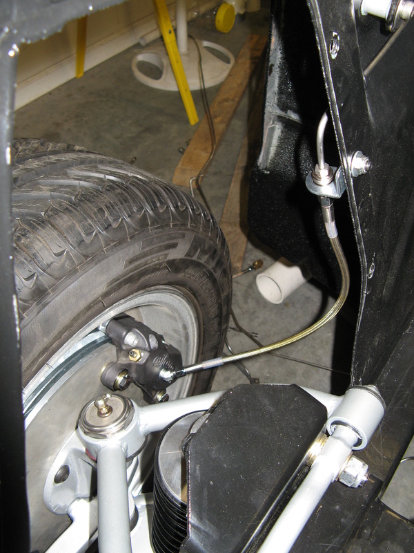
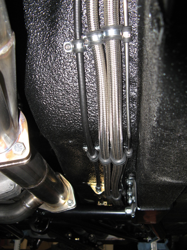
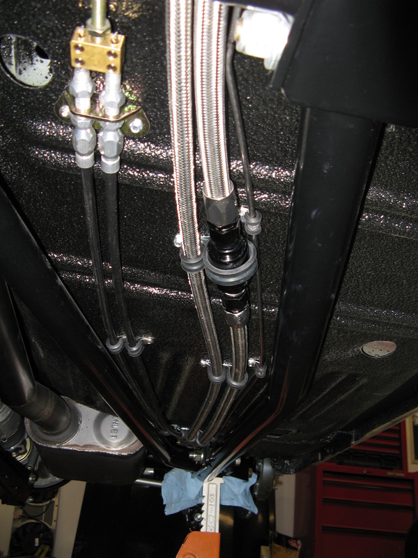
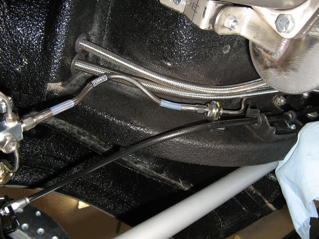
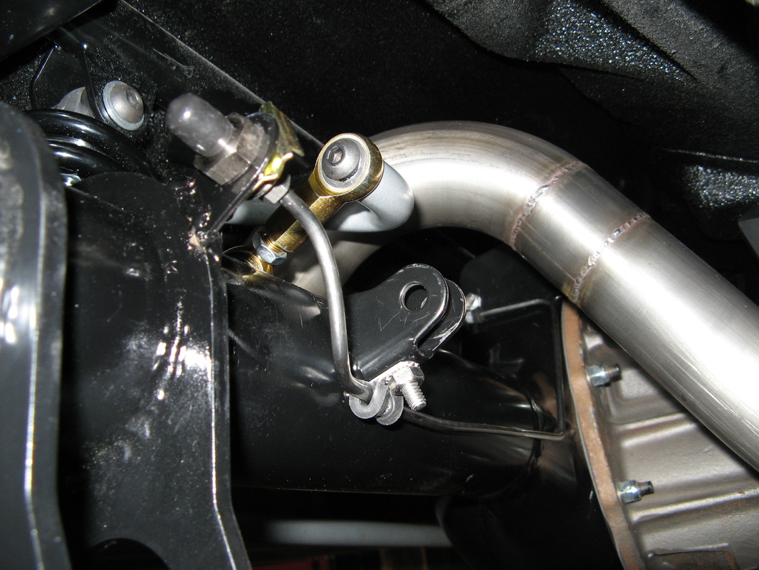
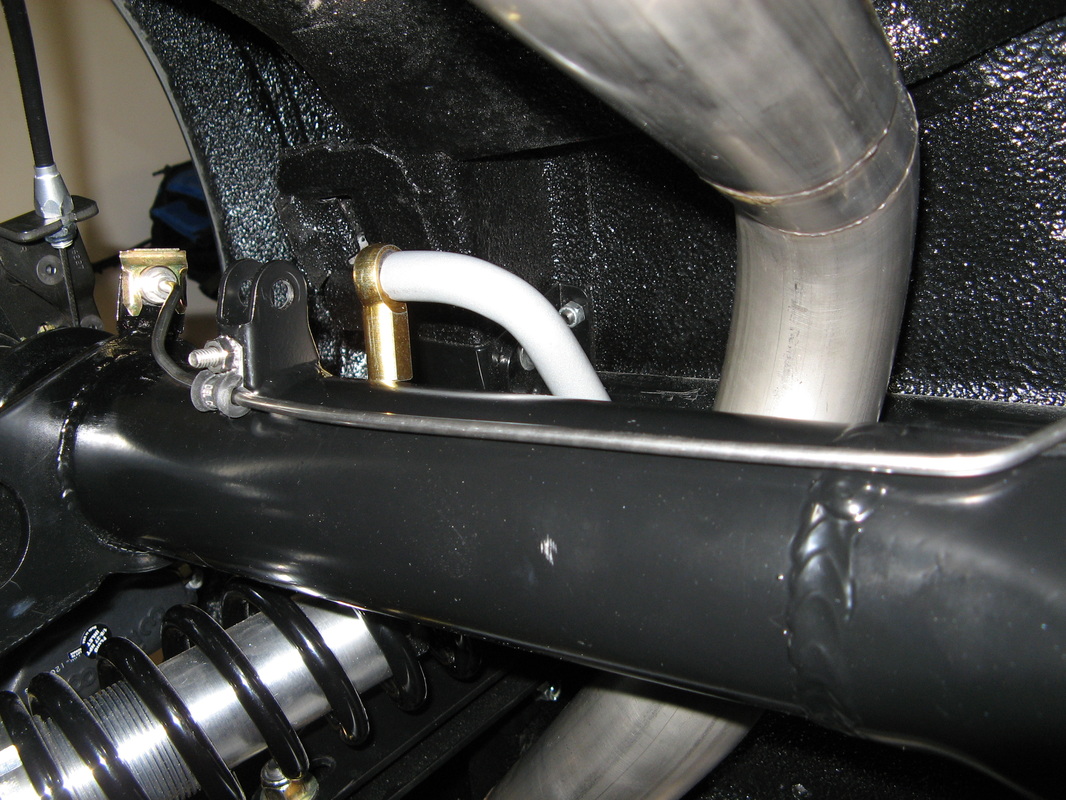
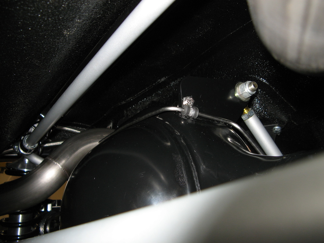
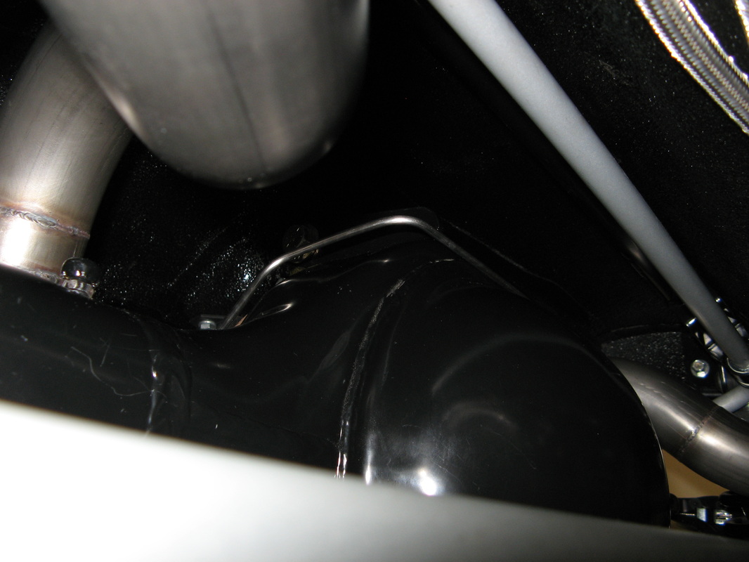
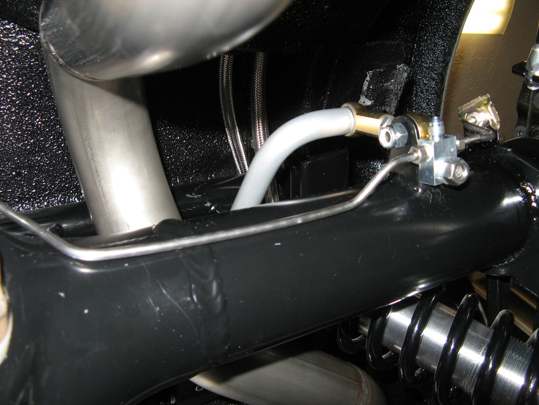
Proportional Valve to Rear Axle
This was an interesting line to run, especially since I waited till the exhaust was done. After a few hours of figureing out where to locate the flex line from the body to the rear axle, I finally started bending up some test segments. I think the hardest part here was that I had to fish the final line over the frame crossbrace. The other bummer was that I had to move all the gas lines over a bit to squeeze in the brake line where it needs to go. But overall I was very happy with how it all came out.
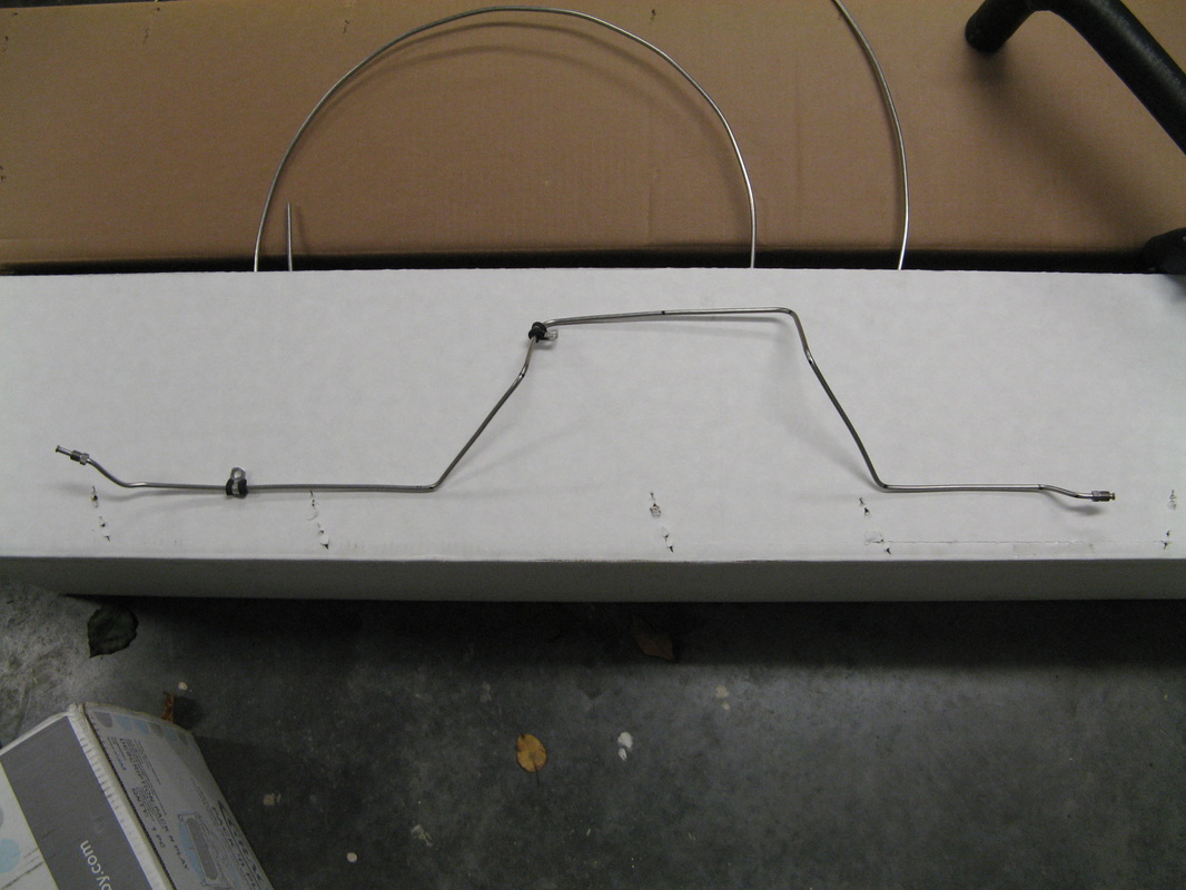
Rear Axle Brake Lines
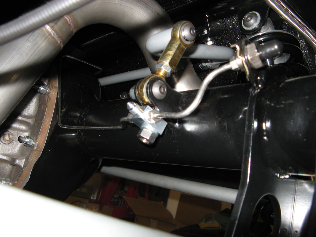
This was one of the trickier lines to bend up. I decided to wait till the exhaust was completely installed to figure this one out. This gave the Barillaro boys the greatest ease in running the exhaust system. The first thing I had to do was weld on some tabs to hold the hard line to flex line coupler on each end of the axle housing. Next was to figure out where the flex line from the body would jump over to the rear axle. The cleanest point I saw was to mount a T-block right on the bottom of the sway bar mount. This kept the moving bits out of each other's way, and allowed me to keep the hard line nice and tight against the axle housing. Basically I have two 10" flex lines that go to each caliper and a single 12" line that is going to go from the axle to the body. The interesting part about this line is how I ran it up and around the back side of the pumpkin to keep everything servicable.
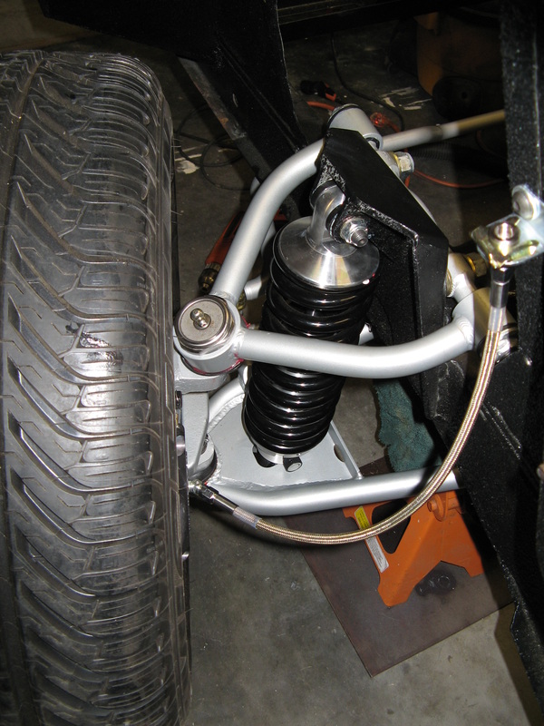
Finally the Brake Calipers
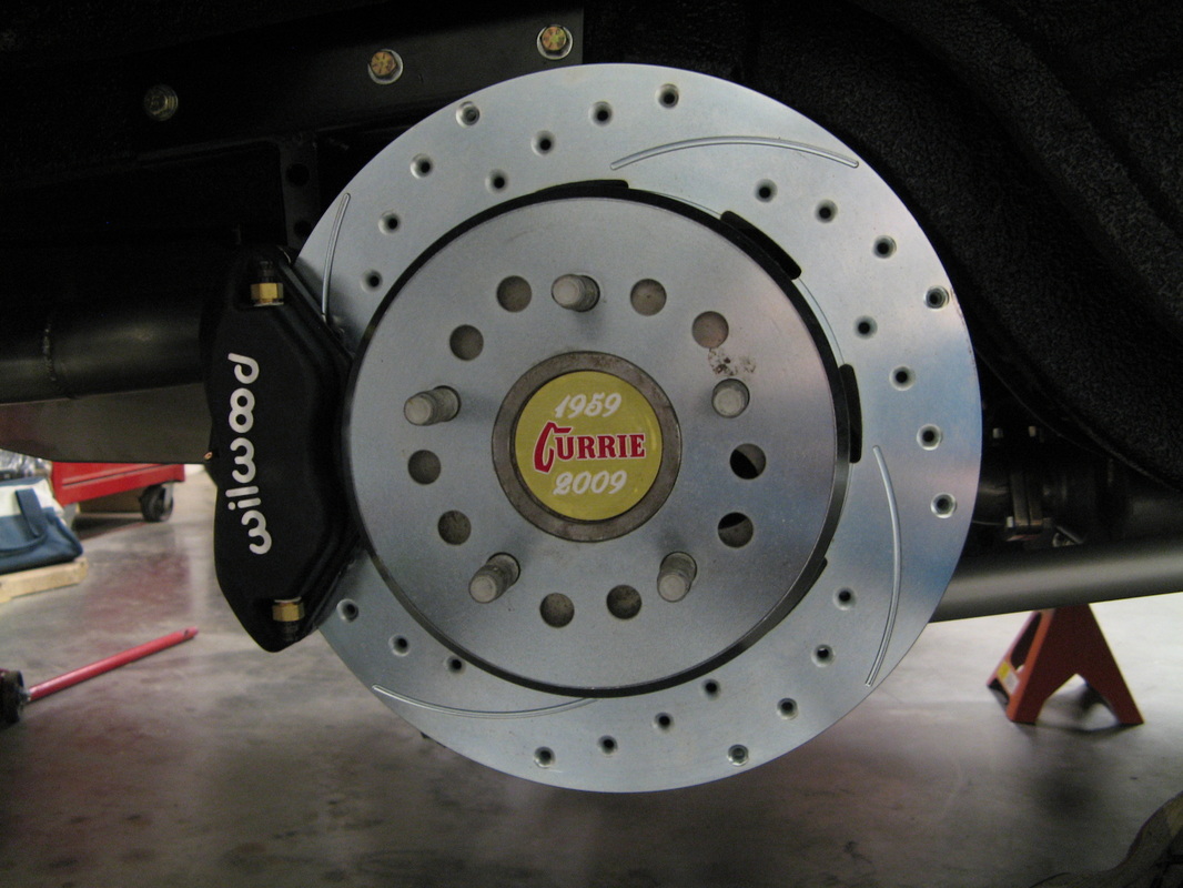
Here you can see just how big these rotors are. These are almost 2" bigger than the original rotors and the drilling and slotting goes a long way to helping with brake fade. Not only that but this setup just looks plan good. Technically these are Wilwood 12.19" rotors with four piston Dynalite calipers. I opted for the larger brakes in the rear also so that I would have fixed calipers instead of floating ones. That and now I have the same brake pads all the way around the car. Makes maintence alot easier. The other thing nifty about this setup is the internal drum parking brake in the rear brakes (see picture).
