Levers of Goodness - Australian Style
Well my pedals from RRS finally arrived. Somehow a 3-week lead time turned into about 4 months, but at least there are here. Anyways, let me give you a bit of background on this setup:
I original purchased a master cylinder from a 04 Cobra to use on my car. This was a hydro-boost setup that instead of using engine vacuum to increase the braking pressure like most power brakes use, it uses the power steering pump. This allievates alot of problems if you have a very radical cam and not producing enough engine vacuum to be of much use. If that happens you can always add an electric vacuum pump to assist the brakes. Anyways, the hydro-boost part of the brakes in much smaller in diameter than the vacuum-style ones so I though with this wider engine that I would need it. I've seen a few pictures of a '66 mustang with a 4.6L Cobra motor, with normal vacuum-assisted power brakes. But to my knowledge I have never seen a 5.4L GT500 motor in a '66 mustang. So with a blind guess, about $100 on ebay, and presto hydro-boost for a '66 mustang. Well at least that what that plan was...
I original purchased a master cylinder from a 04 Cobra to use on my car. This was a hydro-boost setup that instead of using engine vacuum to increase the braking pressure like most power brakes use, it uses the power steering pump. This allievates alot of problems if you have a very radical cam and not producing enough engine vacuum to be of much use. If that happens you can always add an electric vacuum pump to assist the brakes. Anyways, the hydro-boost part of the brakes in much smaller in diameter than the vacuum-style ones so I though with this wider engine that I would need it. I've seen a few pictures of a '66 mustang with a 4.6L Cobra motor, with normal vacuum-assisted power brakes. But to my knowledge I have never seen a 5.4L GT500 motor in a '66 mustang. So with a blind guess, about $100 on ebay, and presto hydro-boost for a '66 mustang. Well at least that what that plan was...
Yep...I'm beginning to dread measuring things.
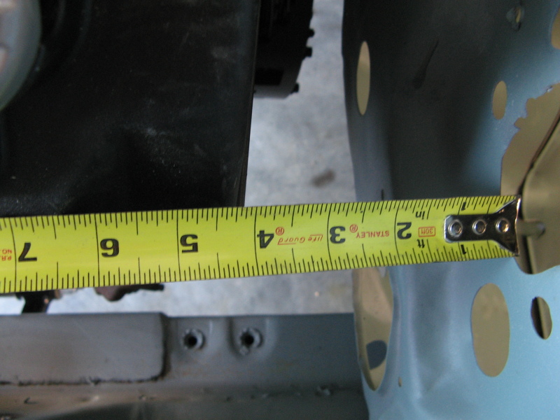
Well the 5.4L GT500 motor is quite a bit wider than the 4.6L Cobra motor so any hope of installing a brake booster in the engine bay is all but evaporated at this point. I don't know of any power braking setup that are shorter than 4". Needless to say that the hydro-boost won't even help here since the engine is sitting directly in the path of the normal brake pushrod. So I was considering pushing the firewall in for a breif moment, but that would of ate way too much room in the passenger cabin. It was about this time that I remember seeing a nifty braking setup somewhere on the internet.
Aussies to the Rescue
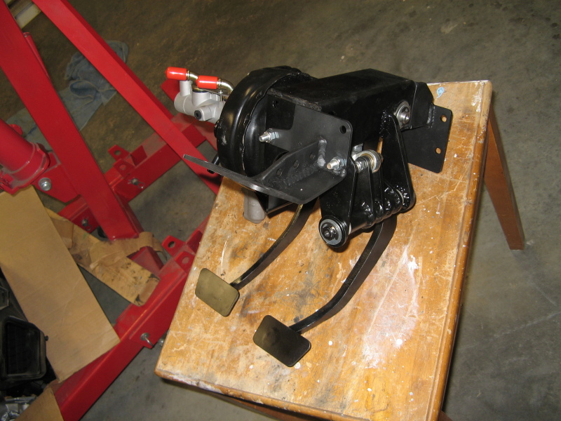
When I was looking for suspensions I came across RRS and checked out their coil-overs for the front end. I ended going with a TCI front suspension instead because I needed to cut out the shock towers for the engine. But while I was there I saw they had an underdash brake booster setup that makes for a "clean" engine bay. Well, I was looking at their datasheet on it and they had pedals from a GT500 so I knew they had the same problem as me in a '67 mustang. Come on guys, just say it, the GT500 motor is freaking huge. Anyways, the really neat thing about this RRS setup is that the brake pedal connects to a vacuum-assisted power booster by a bell-crank linkage. This converts the fore-aft movement of the pedal to a side to side movement. Thus the brake booster can be tucked nicely under the dash. That and a hydralic clutch pedal to match the hydralic throw-out bearning in the transmission. It was worth every bit of the $2,300 I paid for it.
But first the steering
Well I've done quite a bit of work on the firewall so I wanted to get the steering column in before the pedals just in-case the firewall was bowed a bit from all the welding I did. I had to dig through the box of pull-off parts I had laying around to find my dash to steering column mounts. After a few minutes with the wire wheel they looked all nice and shiny again. This picture shows how the mount from the pedals connects to the steering column mounts. This would actually be clamping through the dash panel also. The mount from the pedals is still black. You can also see the ring shims that I need to use to get this to clamp to my new steering column. TCI suggested that these be tack welded to make it easier to bolt it. I totally agree, so here is how I held them together so I could tack weld them. I think there are about 8 pieces that you need to hold together before you can run those two bolts in. So now I'm down to only holding 6 things. :-)
Stupid bracket
When I ordered my braking kit I told them it was for a '66 mustang LHD (left-hand drive). Though they got the main assembly right, I think this bracket is for a RHD '67 mustang. Not only is the back plate backwards (there are two holes on the left and one on the right on the main braking assembly), but it's way too long. Somehow waiting around for another bracket just isn't what I wanted to do this weekend. So with the grinder and welder in hand, here we ago again...
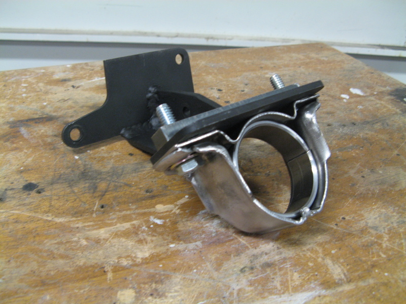
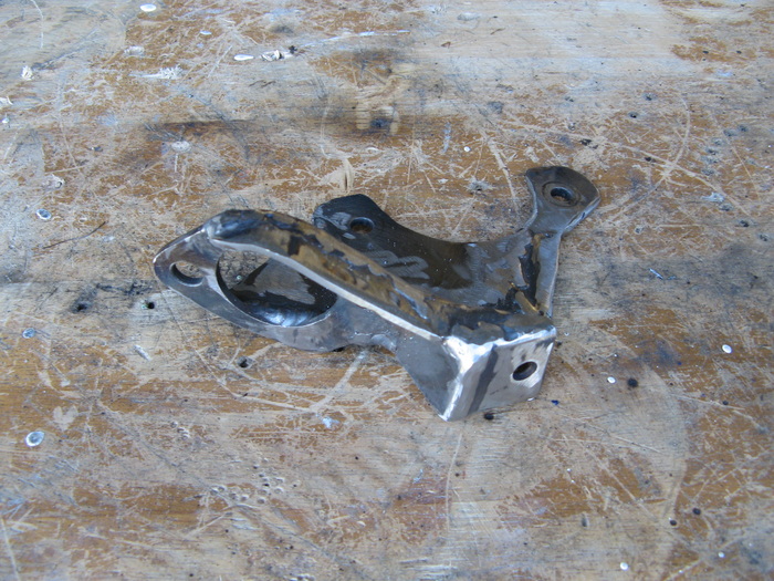
Not quite the bracket I need
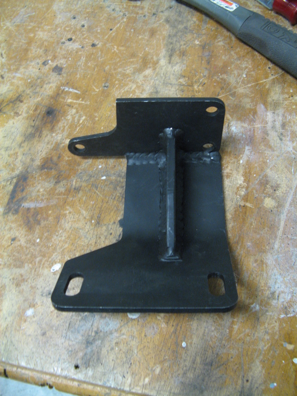
Here's a picture of the unmodified bracket. On the bottom are two slotted holes that bolt to the dash. The plate on the top of the picture is technically backwards from the bolt pattern on the main braking assembly. It was kinda sad to have to cut into these really nice TIG welds, but if it doesn't fit, I'll make it fit.
Rearranging things the way they should be
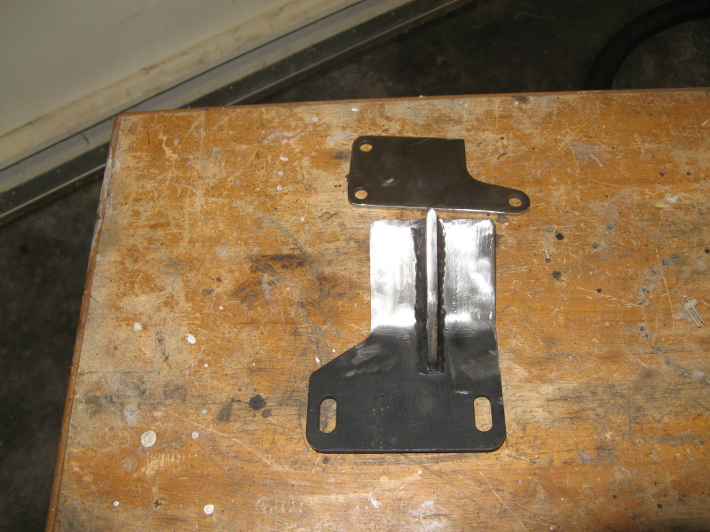
Here I seperated the plate from the rest of the bracket. This is the way that it needed to be welded on in the first place. The idea here is to bolt that plate to the main brake assembly and then start to trim the rest of the bracket down until the holes in the dash line up correctly. Simple enough, except that as I figured the firewall was bowed a bit, so I had to put alot of pressure on the braking assembly to get the firewall to twist back out. So here I am fighting the firewall twist, trying to keep the braking assembly level and cutting the bracket down to length. The fun never stops.
The annoying flange
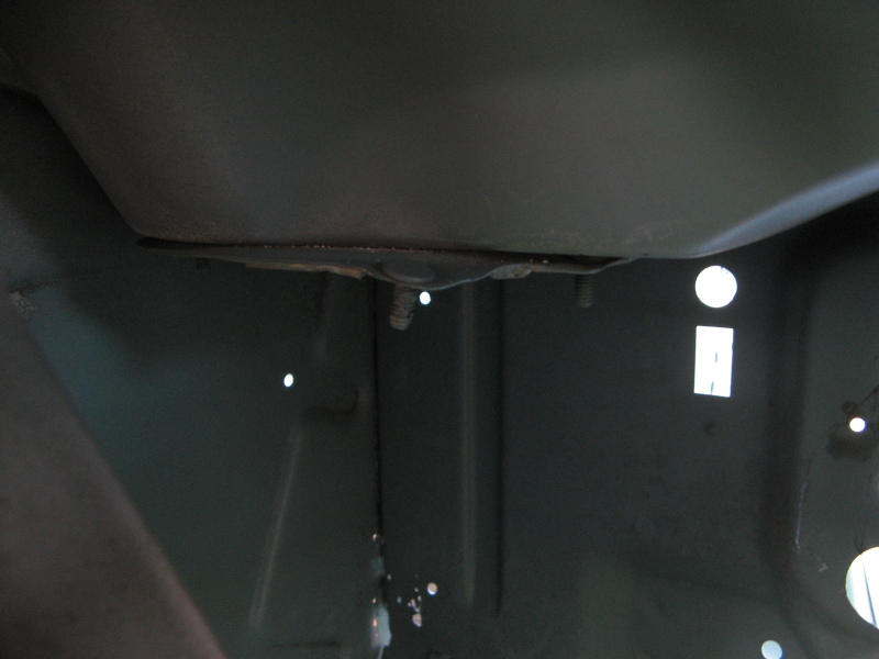
Originally there is suppose to be an air divert here that looks alot like a big coffee can. I never really had good luck out of it and when it rain there always seemed to be a bit of water that would leak down here. While testing the pedal assembly the brake booster would always hit this flange. So I figure to just go ahead and cut the flange off and fix the problem.
Really nice Cowl Vents
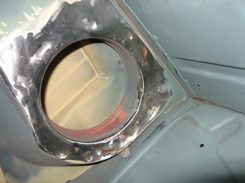
I took about 2 hours with a cold chisel and hammer, but I slowly worked all those spot welds off. After a bit of finish grinding and sanding I was surprised at how good these cowl vents where. Usually they are rusted through, but these are in really good shape. I think the reason I kept getting water in here was the couple of screw holes that are directly above the vent weren't sealed right. That and the very large 1" hole that never had a plug in it. Ahh go figure that one. Anyways, I've got a clean cowl and now room for the brake booster.
Tack welds of Doom
Well with everything twisted into place I was finally able to get a C-clamp to hold everything tight. Now all I have to do is get a couple of tack welds on the bracket so that I can finish weld it on the bench. Yep, gotta tack weld it through the dash. So with the gas turned on, the wire speed at a blistering rate, and the heat turned up on the welder, time to get that thing stationary. All I can say is it was much easier said than done.
All welded up
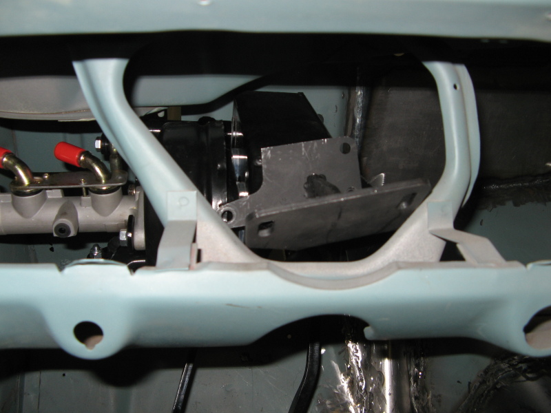
Here the bracket is all welded solid and bolted in. Overall it just took a few hours to bend the bracket a bit more and take about an inch and half out of the length of the bracket. But finally the pedals bolted in nicely.
Solid as a rock
Here you can see everything bolted up. If you glance up a few pictures you can see just how much of that bracket I had to cut off. Basically there were three holes originally, and now I only have two. Here you can also see that nifty bellcrank mechanism to drive the brakes.
Pedals to the Floor
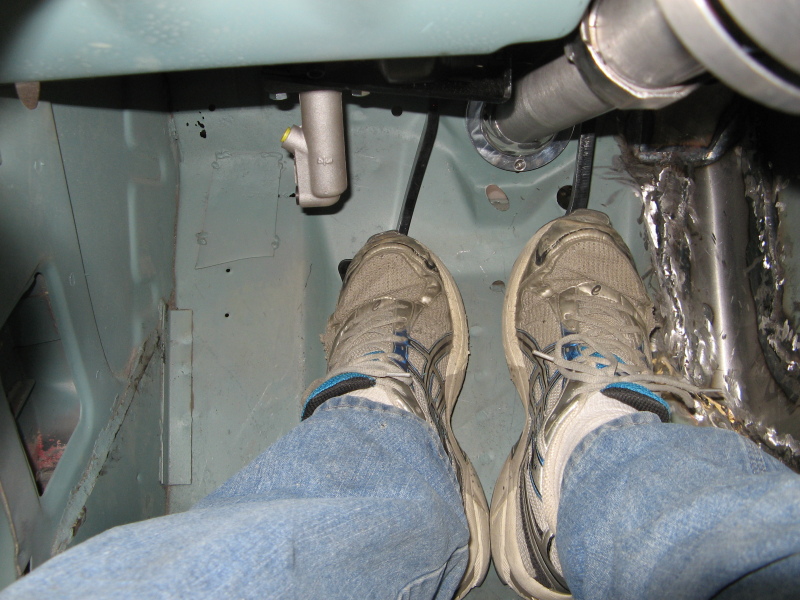
The clutch and brake pedals both had really nice swings to them and came to about 1/2"-3/4" from the floor. This is actually really nice because they won't bottom out on the carpet, and I have full range of motion. That thing you see hanging down on the left is actually the clutch master cylinder. But it's tucked up enough that I haven't had an issue with it.
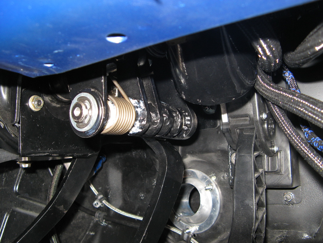
Connecting the Steering
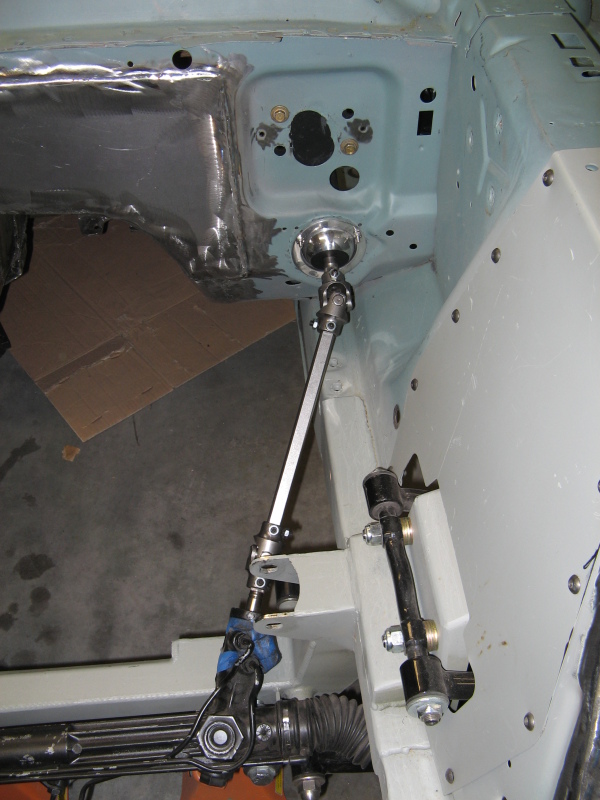
So with the pedals set I cut the steering shaft to the proper length and clamped down the U-joints. I ended up using a IdidIt floor mount for the steering column. That's the odd Ball thing that connects the steering column to the firewall. It's actually a really nice setup. There's these three plates that bit on the the "ball" and sandwich the firewall all at the same time. This allows you to set any angle of the steering shaft with ease. Now hopefully I won't have an issue with the engine and headers with this steering linkage. If not I might have to add another u-joint and jog the steering shaft over a bit. I hope not but I'll find out tomorrow.
The Cockpit
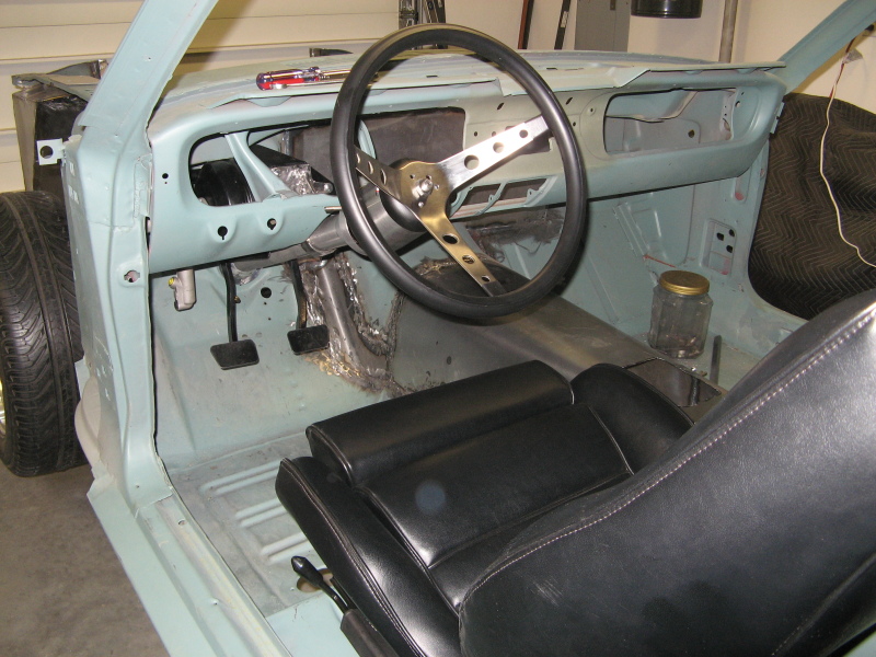
It's so nice to finally start to get a feeling on how this car is going to be. I had to trim the seat frame down a bit because it was just way to high. It's still a bit higher than my original seats, but it's ok for now. Now that I got my clutch and brake pedals in I can get to lining up the gas pedal. But that's going to be another adventure for tomorrow.
Bet you wish your Classic Mustang could do this.
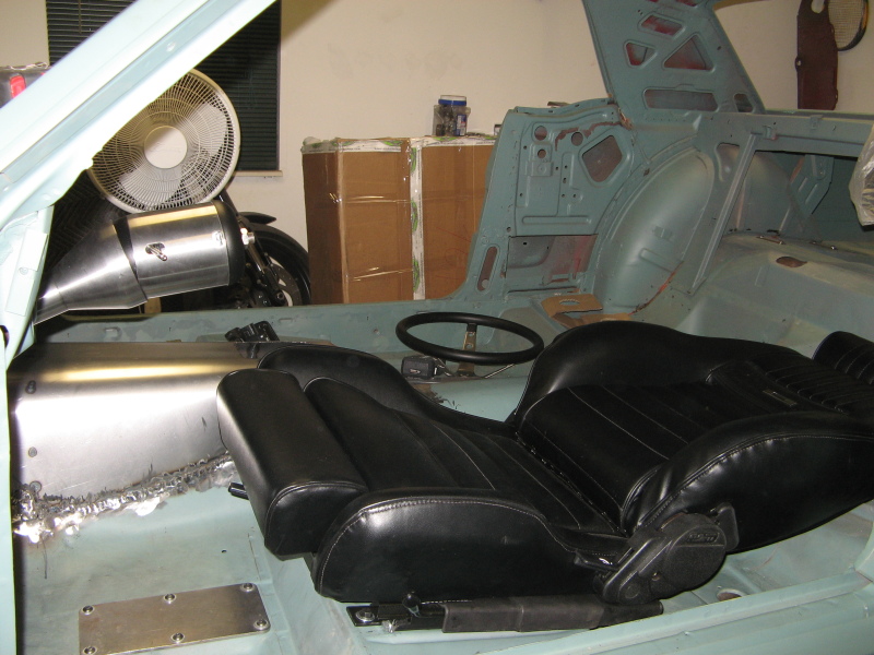
That's right, Tilt Steering column, and reclining seats. Thought I dont' think I'll ever recline that far, it's nice that it can do that. It makes sleeping at the rest stops alot nicer. I'm soo ready to go for a long road trip somewhere and camp out every night.
Another milestone, just a bit closer to the end of the tunnel
Overall I so glad that I came across that pedal setup from RRS. I don't think I could of made this project work without it. It would of taken me a really long time to figure something else out. Other than the bracket goof; this kit was well engineered out and looks really good. I'm still impressed with all the clean welds and adjustable joints. Not to mentioned that ingenious bell-crank mechanism for the brakes. Would I buy it again? Definitely. I just wish they had better communication about their lead times. I'm ok with things taking longer than they are suppose to as long as I'm kept informed with what is going on.
Pedals FINALE
So after a while waiting for the undercoating and engine bay painting, I'm finally able to get those stupid pedals in one last time. Now if you look a few pictures up you will notice how the clutch master cylinder sits way to close for comfort with my big feet. So I decided to crank up the welder for one last go at re-modifing this pedal assembly.
The odd clutch master cylinder
When I look at how much engineering went into getting that master cylinder twisted around, I wonder why they took the easy way out with the clutch. Though it will physically function this way, I've already caught the front of my shoe several times just sitting in the car making noise (yes I've already done that). I looked back on RRS website and saw how nice they placed the clutch on the Right-hand drive version. The problem with the American left-hand version is that the brake master cylinder couldn't go to the right because of the windshield wipers. So that left the power booster and brake master cylinder in the way of normal clutch linkage.
Now for a talk about circles...
Before I just randomly moved the clutch master cylinder, I wanted to figure out 3 things:
1- Why RRS did what they did?
2- How the 2008 GT500 worked its clutch?
3- Compare the first two items together to get the best location to relocate the master cylinder to.
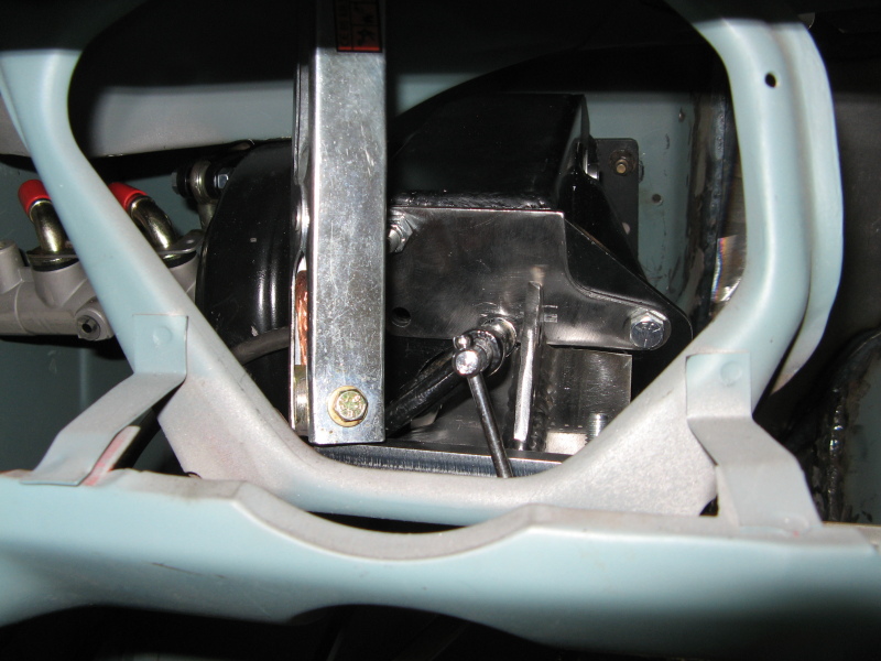
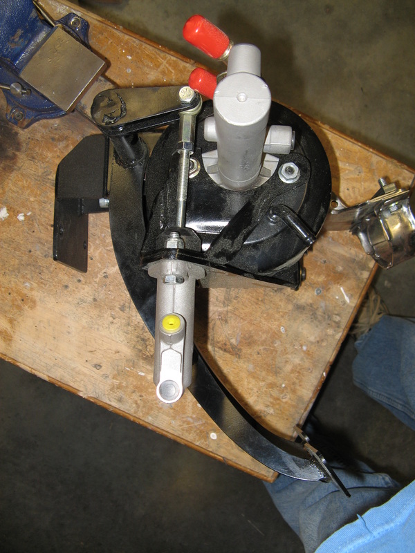
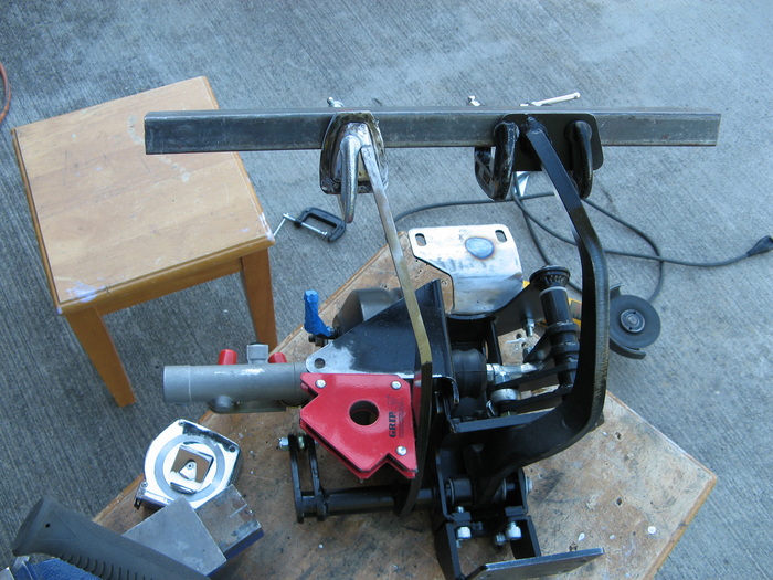
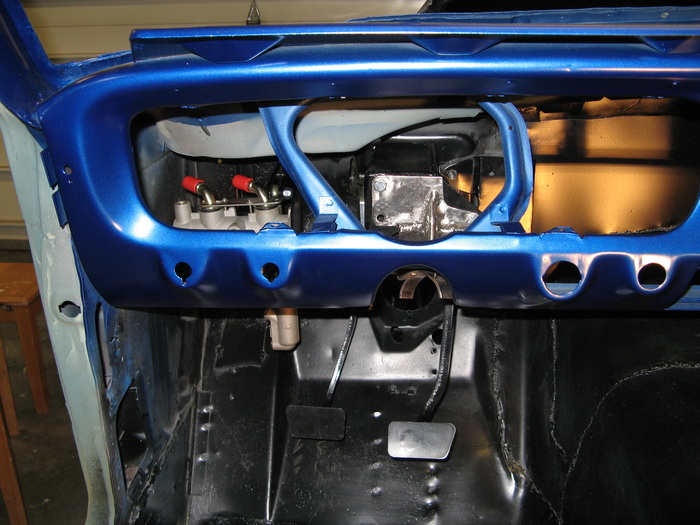
First off, from what I can tell RRS wanted to give the best linear push to the cylinder, so they just tucked the cylinder in tight to the power booster and called it good. The main problem with this is how close your shoe comes to the clutch cylinder. Just by rotating the cylinder by 90 degrees, they could of gained about 1" of vertical clearance. This would of allowed the cylinder bolts to sit beside the power booster instead of below it. Now if you look at the first picture below, notice how the arm from the clutch pedal to the pushrod for the clutch cylinder is a little less than 90 degrees. The reason behind this is during the "stroke" of the clutch pedal, the bolt that joins the clutch arm to the pushrod is moving along the outside of a circle (2.5" radius to be exact). Having the start position a little less than 90 degrees, will allow the end position to be a little more than 90 degrees. This allows the pushrod to move linearly in the straightest line between two points on a circle, giving maximum push with minimum pedal travel.
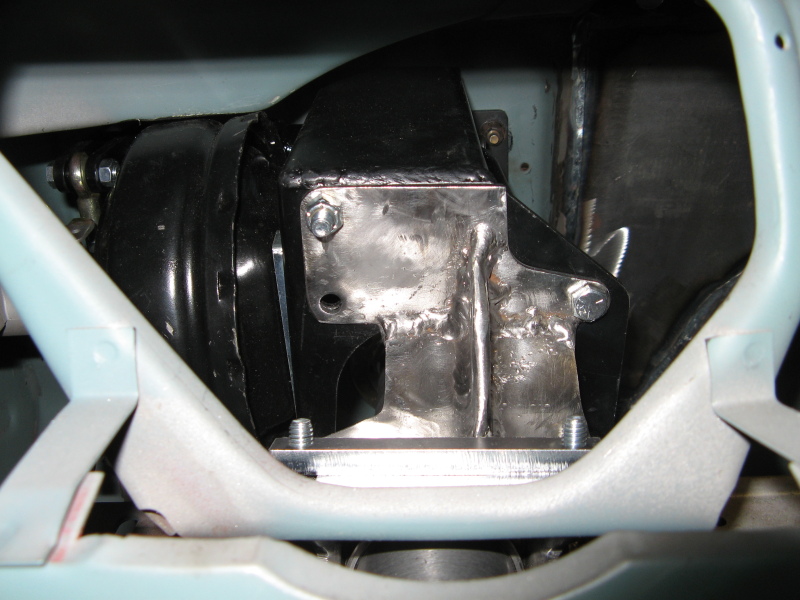
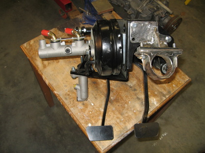
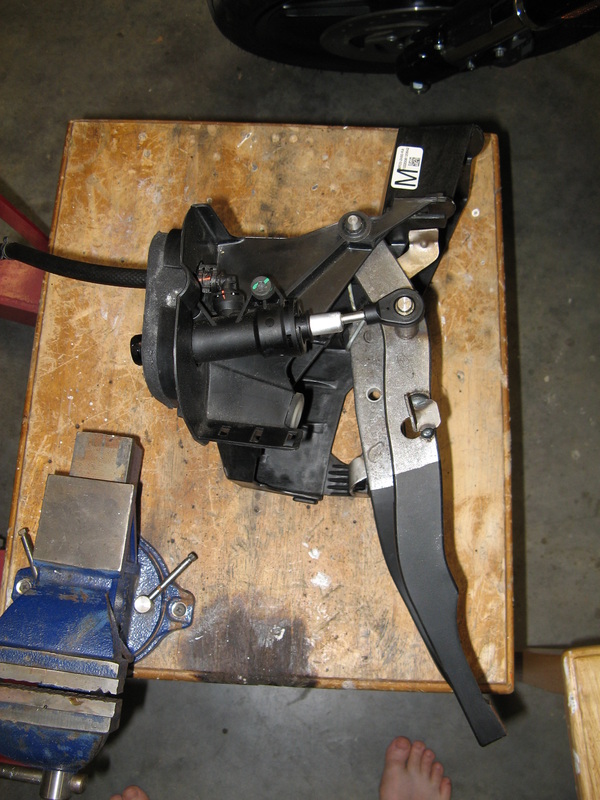
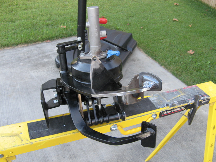
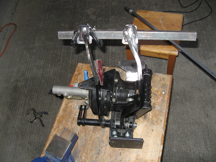
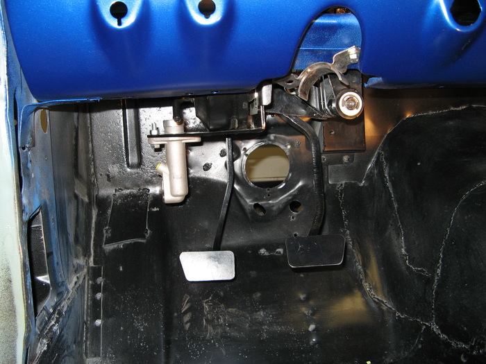
The GT500 setup is what you would normally expect in most cars. Here the power booster and brake master cylinders are in the engine bay. Both pedals use a nice simple leaver arm to push straight into the master cylinders. In the second picture below you can see how nice it would be for a straight shot setup like that. The main thing to take away from this is the leaver radius of 2.75", and the total stroke length of 1.125".
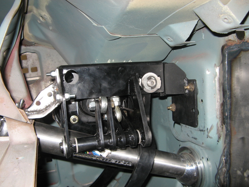
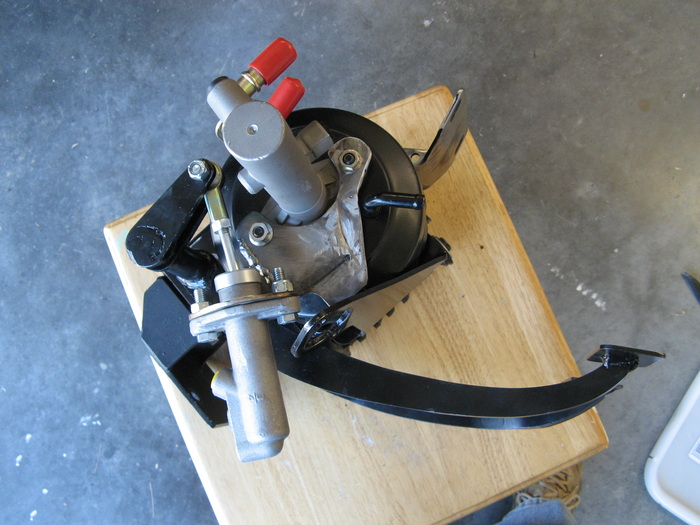
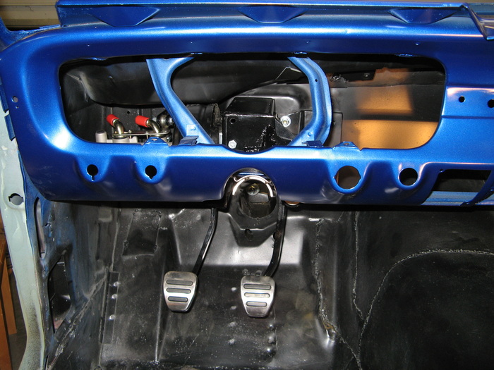
Now for the fun part. I figured the easiest would be to shorten the pushrod as much as possible. That bought me about 2 inches or so. Then I decided it would good to have the clutch master cylinder "lean" away from the driver, so that there is no risk of me getting my shoe trapped between the pedal and the cylinder. In the third picture you can see where I'm figuring on putting it. There are a few issues with this setup in general but I think the benefits greatly outweight those issues:
1- Unknown cylinder size on OEM GT500 pedal assembly. I'm assuming it's an 1" cylinder, so that's my starting point. Though the leaver arm on the RRS setup is a bit shorter than the OEM, I made sure that the stroke length was the same 1.125", so that I would get full disengagment from the hydralic throw-out bearning in the transmission. I can change clutch cylinders if this is an issue.
2- Non-ideal circular pivot movement. If you notice on the third picture, how much lower my starting angle is for the clutch pivot arm, this will reduce the total linear master cylinder pushrod movement I will get with a particular clutch pedal movement. Basically this means I need to push the clutch pedal farther to get the same effect as the OEM clutch pedal. I don't think that is too much issue, since my foot movement is actually less than what the original 66 mustang had. Besides I can always go to a larger clutch master cylinder to midigate this.
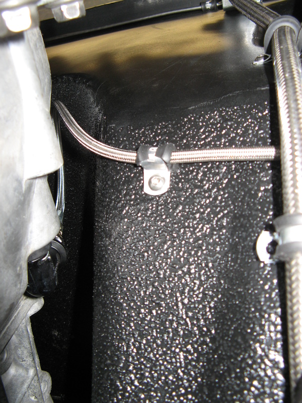
3- Tighter fluid tubing routing. Good thing I bought some extra stainless steel tubing and a nice tight radius bender. You'll see what I can do with this later next week.
1- Why RRS did what they did?
2- How the 2008 GT500 worked its clutch?
3- Compare the first two items together to get the best location to relocate the master cylinder to.
First off, from what I can tell RRS wanted to give the best linear push to the cylinder, so they just tucked the cylinder in tight to the power booster and called it good. The main problem with this is how close your shoe comes to the clutch cylinder. Just by rotating the cylinder by 90 degrees, they could of gained about 1" of vertical clearance. This would of allowed the cylinder bolts to sit beside the power booster instead of below it. Now if you look at the first picture below, notice how the arm from the clutch pedal to the pushrod for the clutch cylinder is a little less than 90 degrees. The reason behind this is during the "stroke" of the clutch pedal, the bolt that joins the clutch arm to the pushrod is moving along the outside of a circle (2.5" radius to be exact). Having the start position a little less than 90 degrees, will allow the end position to be a little more than 90 degrees. This allows the pushrod to move linearly in the straightest line between two points on a circle, giving maximum push with minimum pedal travel.
The GT500 setup is what you would normally expect in most cars. Here the power booster and brake master cylinders are in the engine bay. Both pedals use a nice simple leaver arm to push straight into the master cylinders. In the second picture below you can see how nice it would be for a straight shot setup like that. The main thing to take away from this is the leaver radius of 2.75", and the total stroke length of 1.125".
Now for the fun part. I figured the easiest would be to shorten the pushrod as much as possible. That bought me about 2 inches or so. Then I decided it would good to have the clutch master cylinder "lean" away from the driver, so that there is no risk of me getting my shoe trapped between the pedal and the cylinder. In the third picture you can see where I'm figuring on putting it. There are a few issues with this setup in general but I think the benefits greatly outweight those issues:
1- Unknown cylinder size on OEM GT500 pedal assembly. I'm assuming it's an 1" cylinder, so that's my starting point. Though the leaver arm on the RRS setup is a bit shorter than the OEM, I made sure that the stroke length was the same 1.125", so that I would get full disengagment from the hydralic throw-out bearning in the transmission. I can change clutch cylinders if this is an issue.
2- Non-ideal circular pivot movement. If you notice on the third picture, how much lower my starting angle is for the clutch pivot arm, this will reduce the total linear master cylinder pushrod movement I will get with a particular clutch pedal movement. Basically this means I need to push the clutch pedal farther to get the same effect as the OEM clutch pedal. I don't think that is too much issue, since my foot movement is actually less than what the original 66 mustang had. Besides I can always go to a larger clutch master cylinder to midigate this.
3- Tighter fluid tubing routing. Good thing I bought some extra stainless steel tubing and a nice tight radius bender. You'll see what I can do with this later next week.
Just one more finishing touch
So once I figured out the clutch master cylinder placement, I went to work with the welder and grinder. Just a few short hours later I had a really nice and strong bracket made up. It actually looks really good, expecially with some black paint on it. Oh yah, I've been eyeing those OEM GT500 pedals for a while. I think the stainless and rubber setup they have is awesome. That and the gas pedal the engine ECM needs already has a matching cover on it. Two birds with one stone I say. Anyways, here's the quick build-up on what all I had to do.

Finally a good looking Pedal Setup
So after all of the reconfiguring, here are the before and after pictures. Notice how nice the underside of the dash looks now. Now I don't have to worry about jamming my feet down hard on either of these two pedals. Oh yah one more thing, when I was welding the new foot pedals one I shifted them to the left a bit to give my gas pedal a bit more breathing room. I also spaced them out the same as the 66 mustangs (this is a bit wider than the 08 mustangs). Well, we can go ahead and mark this off the list and finshed.
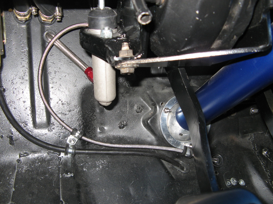
Clutch Line
I couldn't figure out where to put the pictures for the clutch line so I'm doing it here. The main issue I had here was trying to find a fitting to adapt the original bellhousing connecter to a -3AN line so that I can run a flex line all the way to my new clutch master cylinder. Well after digging around the internet a bit I found a place that offers a kit to convert the newer GT500 from the plastic line to a stainless steel line. Well that was good enough for me, because they had some nice brass fittings and it turns out that the flex line they sold in their kit was the perfect length for my setup. The only odd thing about it now is how to bleed the system. According to the Ford Service Manual, you need to vacuum bleed it. Basically pull a vacuum on the clutch resevoir, let the air bubbles come up a bit, and quickly break the vacuum. This will suck the fluid down a little bit at a time. I cheated a bit and bench bled the clutch line all the way to the bellhousing. This saved a bunch of time trying to get the air out of the system. But in the end I have a nice tight clutch pedal. This clutch is alot firmer than my old setup, but hey it's all for a good cause (that and no Z-bar setup).
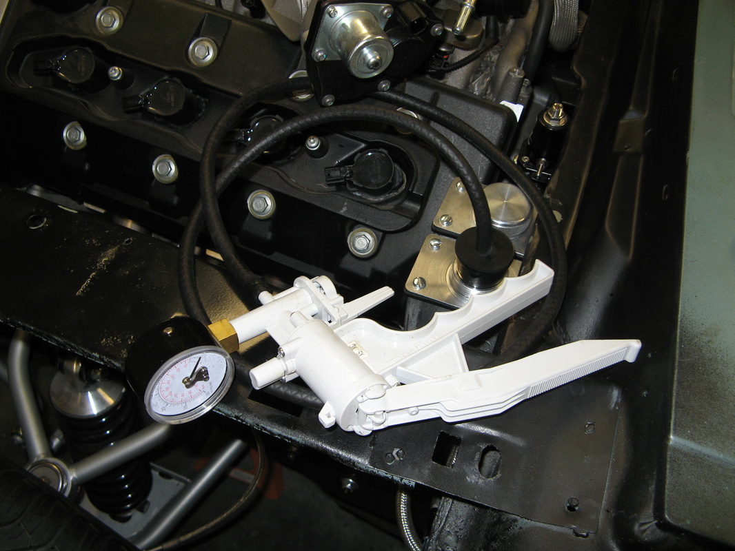
Still messing with the Pedals (hopefully this will be the last)
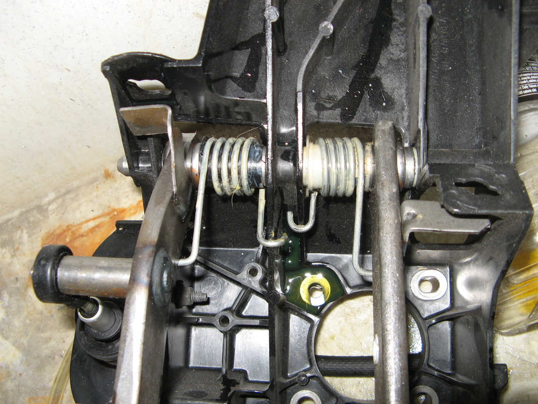
Once the entire braking system was in, I tested brake pressure at all wheels. Without the engine on, I am able to get 1,350psi at all wheels with the pedal all the way down. Needless to say there is amble amount of braking pressure to go around. I dialed the rear down to 950psi to give me a starting point when I do my final tweaking once everything is done. So next thing I did was crank up the engine and see how the power-booster works. Wow, what a difference that makes. It was actually fun to feel how much pressure that superchargers puts in the engine when you rev it. Which gets to a touchy point, I have really touchy brakes. Basically at idle I have a tremendous amount of vacuum which makes that brakes feel really light, almost to the point where the pedal won't return all the way out. This is bad, dragging touchy brakes are bad.
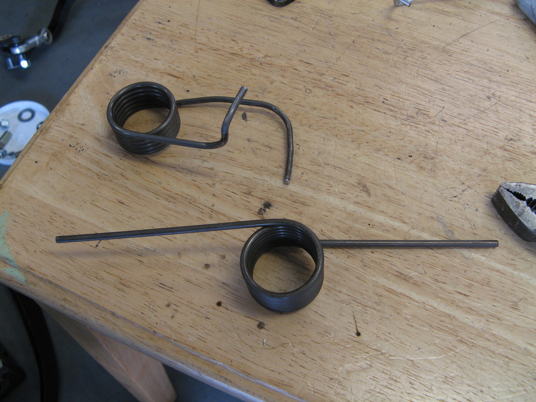
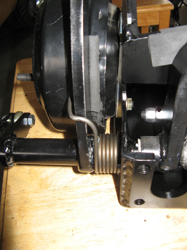
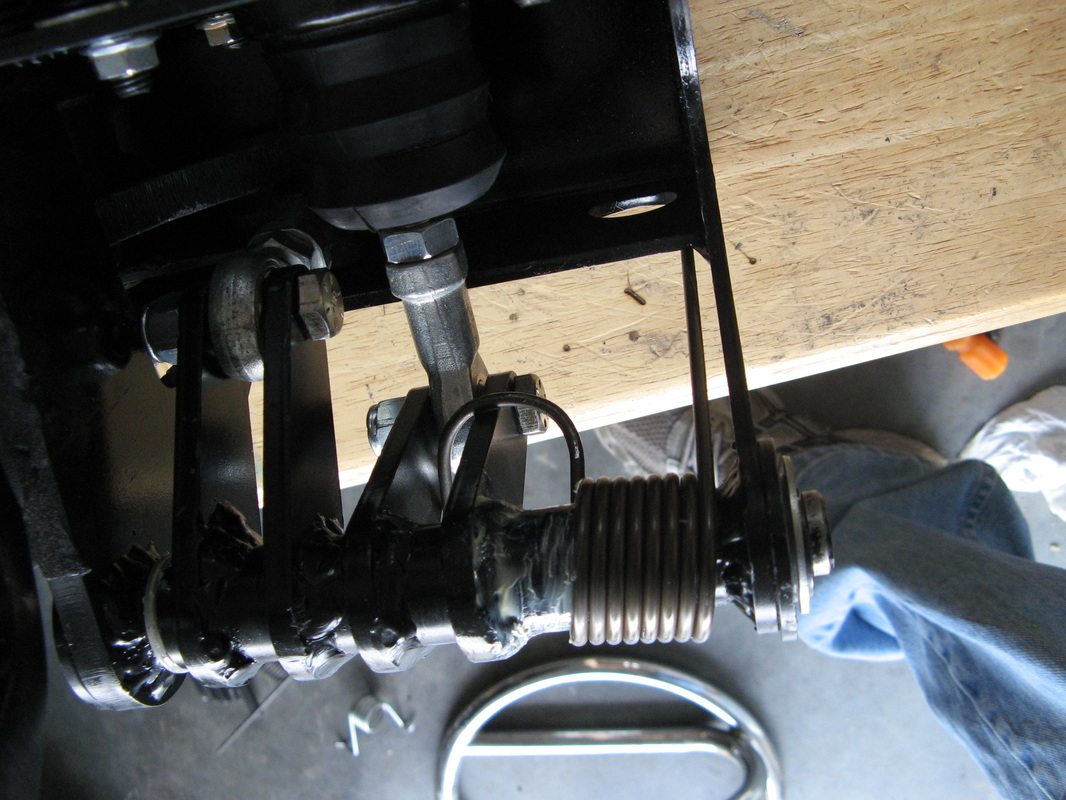
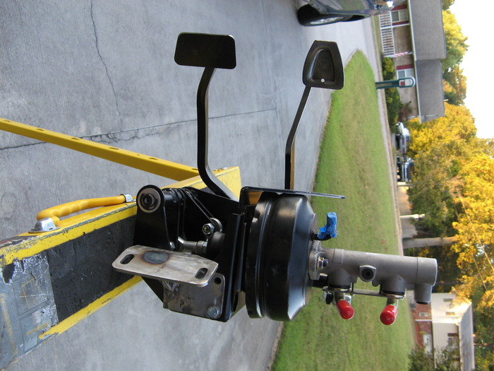
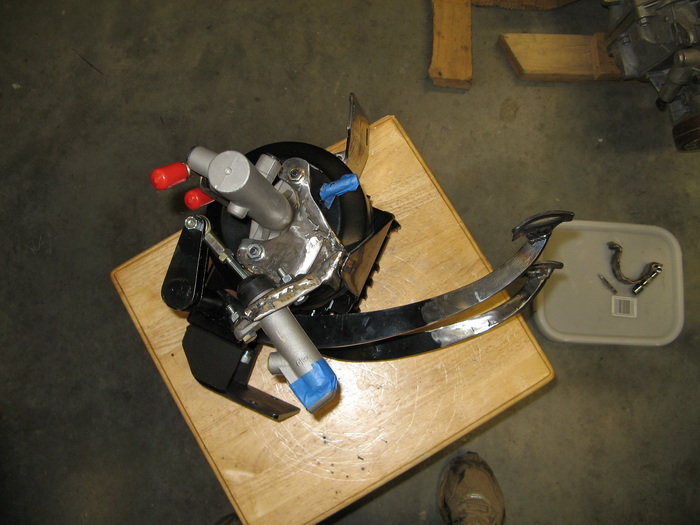
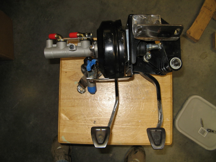
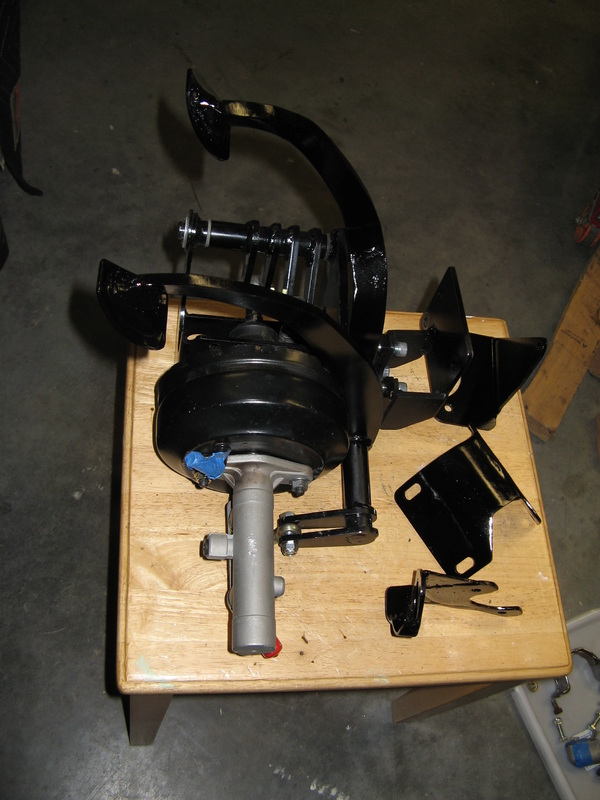
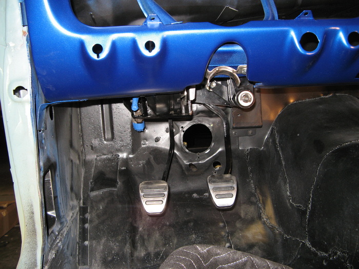
I pondered this a bit, and the only thing different between my current pedal seting and the stock GT500 setup was the addition of tension return springs on the GT500. I first tried to put the GT500 springs on but I was having trouble bracing them. So I went to McMasterCarr to find a comparable tension spring that I could adapt to my setup. After a bit of bending and testing, I final was able to wrestle a tension return spring on both the clutch and brakes. After getting everything back together, now my brakes feel right. No dragging, and just the right amount of resistance to feel confident with them.
This first picture is the GT500 setup, and the other ones are how I retro-fitted my brakes. Hopefully I'm finally finished with brakes.