Engine Electrical
The nice thing about the 2008 Shelby motor, is the single engine and transmission harness. This makes it really easy to keep things clean in the routing department. When I first bought the engine I also bought every bit of wiring out of the donor car. I was going to sit down and slowly remove things not needed until everything was working correctly (I'm an electrical engineer by trade). But after talking with a few people about tuning the car, we decided to get the Ford Racing controls pack for the engine. Let me tell you, $1,800 is well worth the reduction in headache trying to wire up one of these late model motors. That and the power distribution box is alot smaller than the OEM version. With that being said, I still needed to modify the engine harness to suit my build. Here I'll show you what I changed and why.
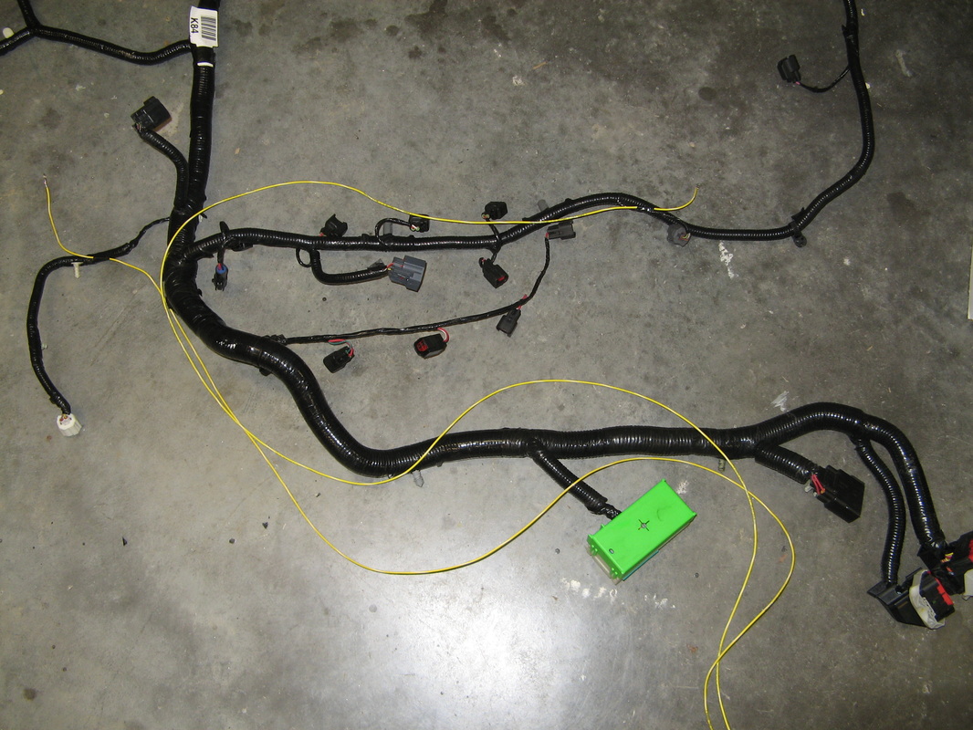
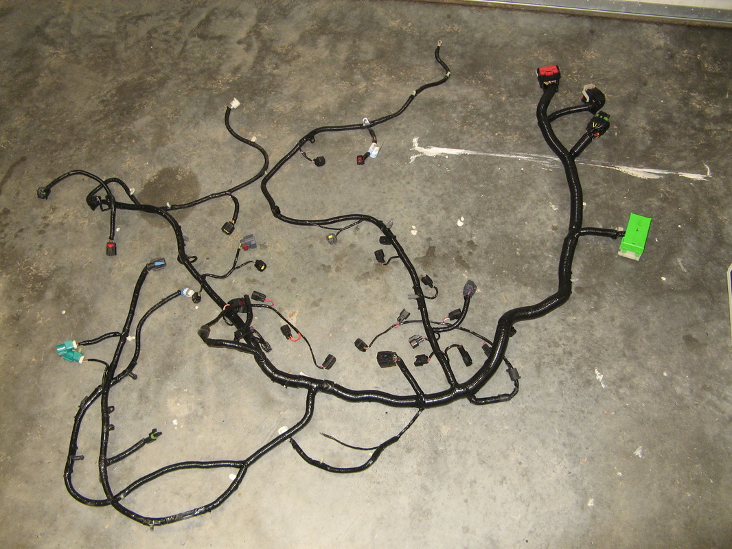
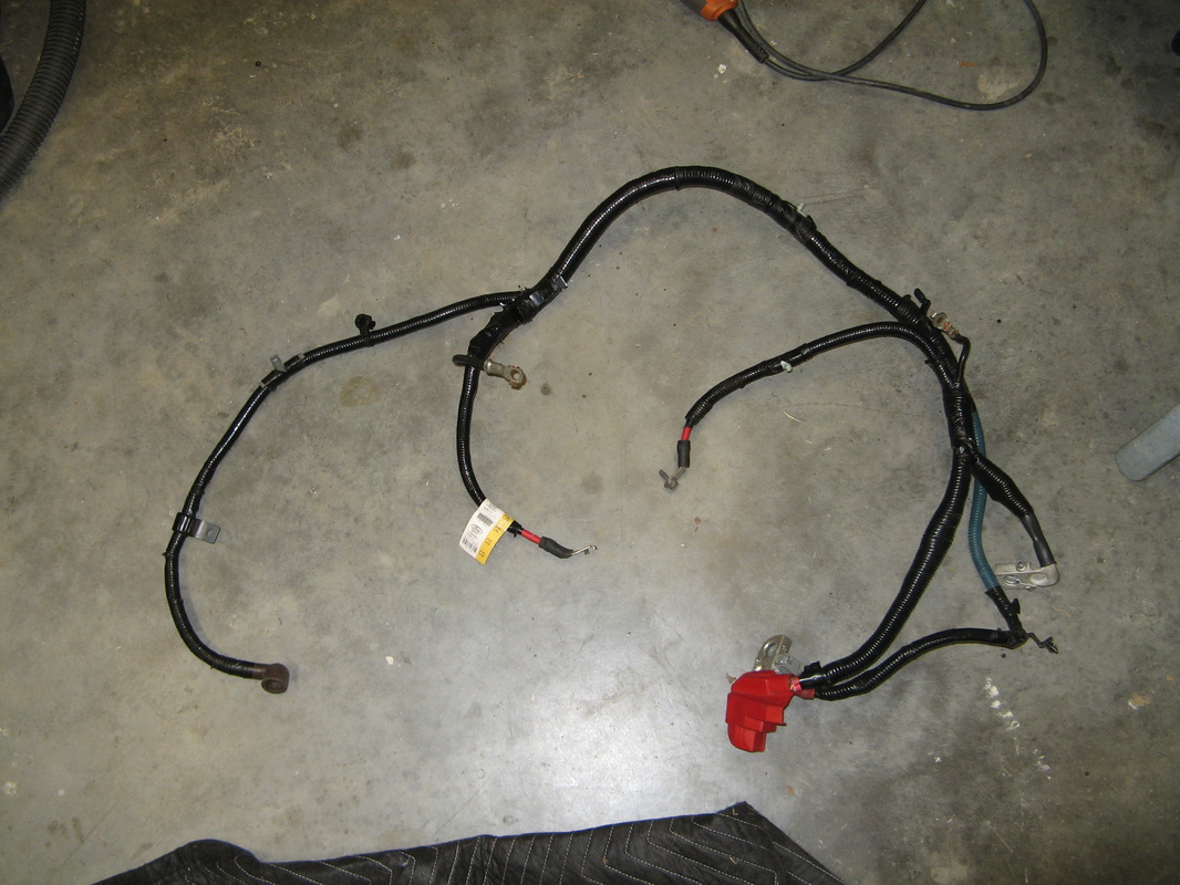
Starting pile of mess
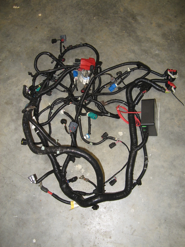
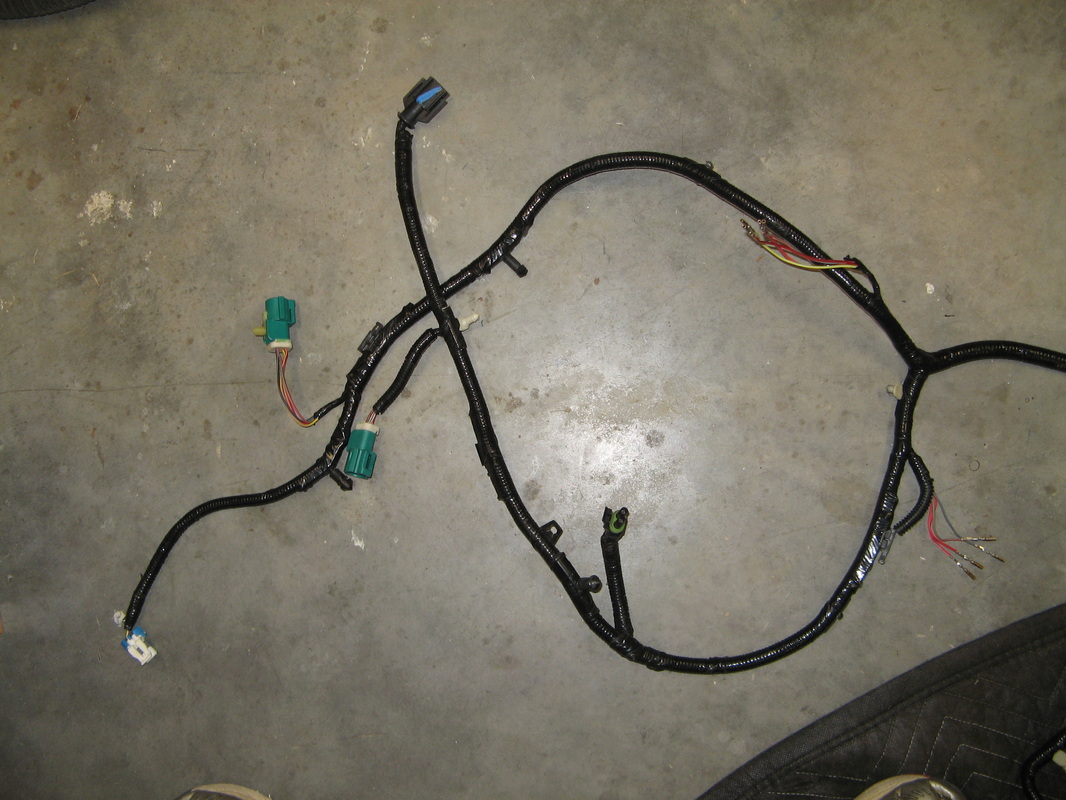
To start with, here is the OEM harness off the engine. As you can see it's a big pile of stuff. I have to give Ford props here, though. They did a great job of adding restraints to keep the harness close to the engine and made it very nice to work on. The black box on the right is the new power distribution box. This houses the fuses and relays to run just the engine. Now the fun part of this is that I'm very meticulous with wiring and I enjoy soldering cable (go figure it's an hobby). Word of caution here, I'm using a 2008 Shelby GT500 5.4L engine harness, colors may change during the years, etc.
To Do list
There are basically five things I want to change about this harness to get it to work with my setup.
1- Relocate O2 sensors
2- Add output for Reverse Lights
3- Add Oil pressure sender
4- Add Temperature sender
5- Remove extra terminals for heavy power cables
1- Relocate O2 sensors
2- Add output for Reverse Lights
3- Add Oil pressure sender
4- Add Temperature sender
5- Remove extra terminals for heavy power cables
1- Relocating the O2 sensors and Adding Output for Reverse Lights
Once Jim finished up with the exhaust, I knew that I need to change the location of the front O2 sensors to work with the new location. I could of bought extenders, but I wanted a more OEM look. So I bought the 2008 Ford Mustang wiring diagram book and went to work. Looking at the original layout, the new O2 sensors would plug in very nicely where the rear-O2 sensor plugs are currently. To do this I would have to change the actual connector body out and rewire a few things to get it to work. For some reason the Ford controls pack does not pigtail out the reverse lights, so I'll take care of that at the same time.
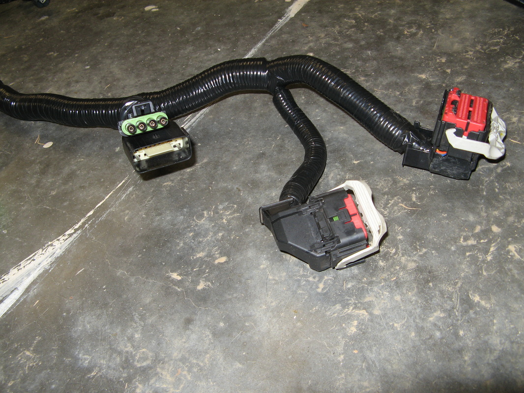
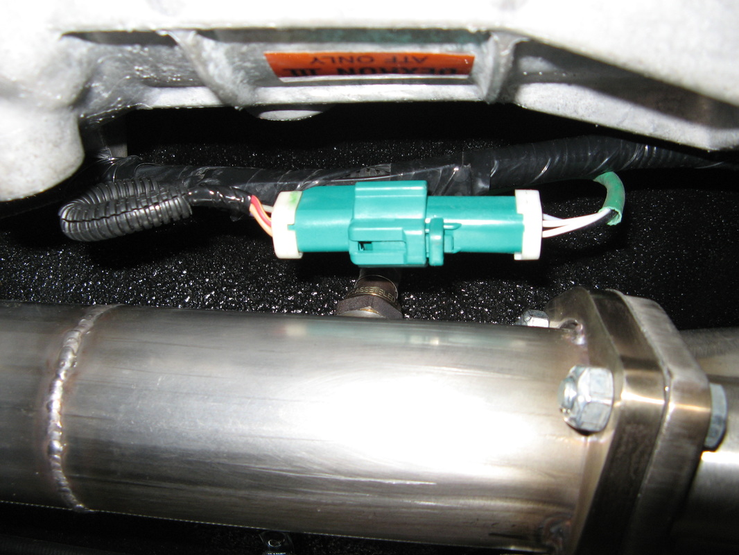
1.1 - Original Layout
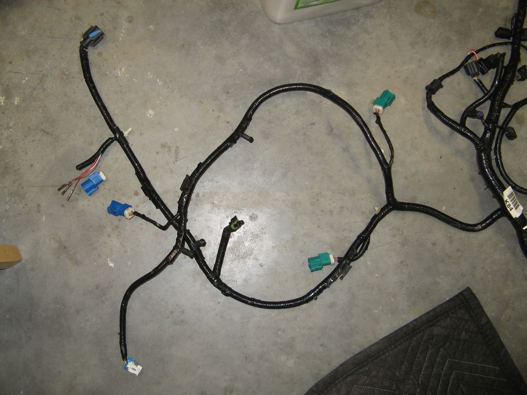
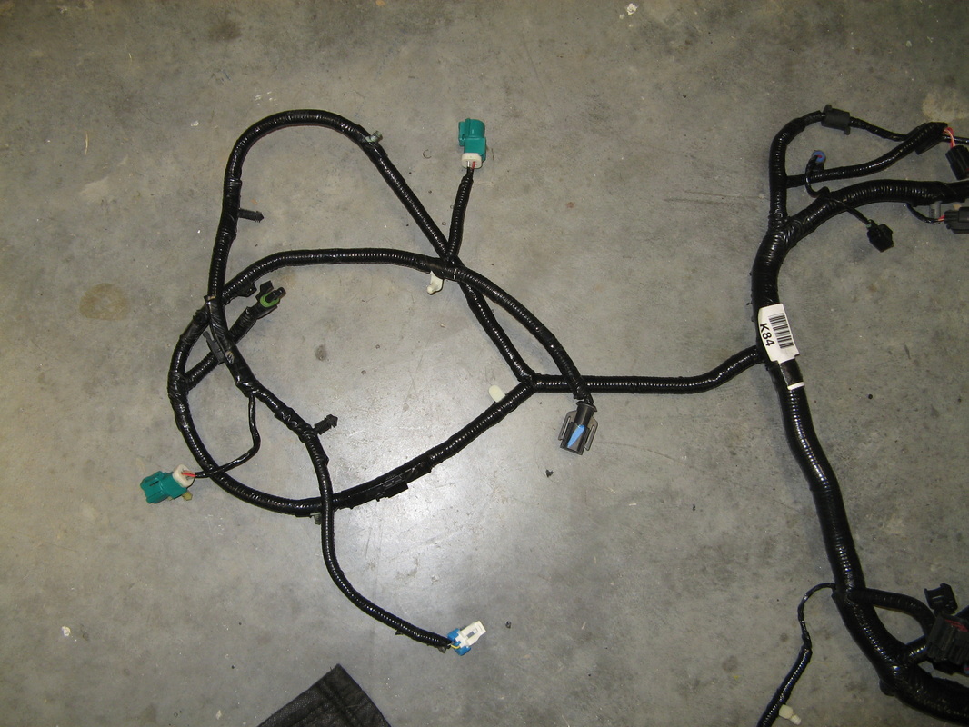
Here is the original transmission layout. The blue connectors are the rear-O2 sensors (ususally plugged into the Catalytic Converter). While the green connectors are the front-O2 sensors. Basically we need to mover the Front green connector body to the rear locations, and then rewire a few wires to get it to work correctly with the ECU. Now with any of these OEM connectors, there is always a little lever somewhere that snaps into place to hold the electrical pin in. I think with the O2 sensors there was a lock on the inside of the connector that you have to pull out, and then you can hold back each lever to get the pins out.
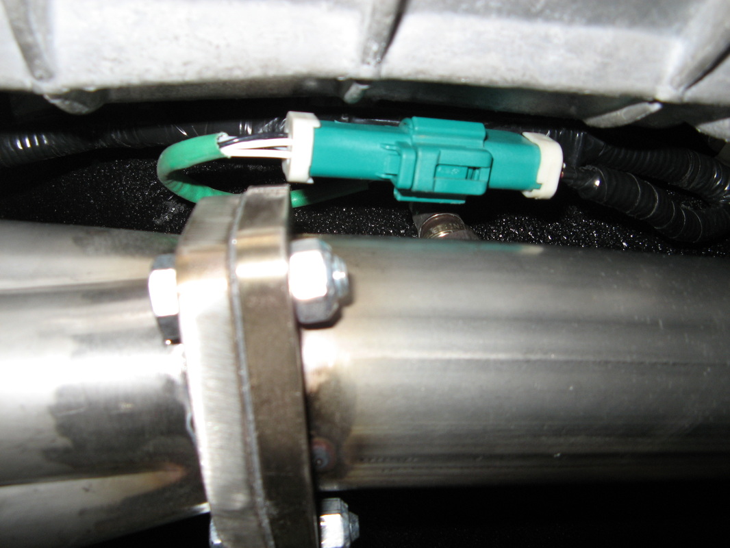
1.2 - Front O2 connectors Moved to the rear
For the left O2 sensor the pinout is:
1-Tan/Yellow (TN-YE)
2-Red/Yellow (RD-YE)
3-Violet/Light Green (VT-LG)
4-Grey/Red (GY-RD)
For the right O2 senso the pinout is:
1-White/Black (WH-BK)
2-Red/Yellow (RD-YE)
3-Red/Light Green (RD-LG)
4-Grey/Red (GY-RD)
Now just for reference, the Red/Yellow is +12V supplied in run/start. the Grey/Red is signal ground. These two wires will be in the same spot on either of the Blue or Green connectors.
1.3 Rewiring the splices
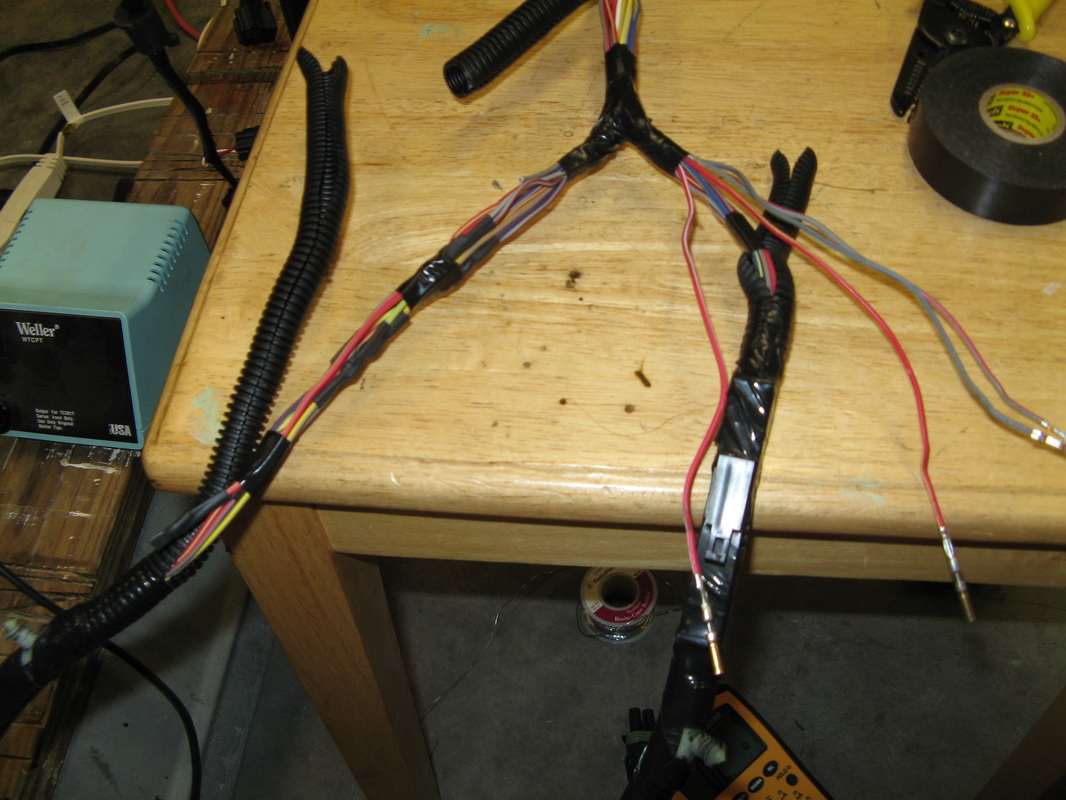
Now for the fun stuff. Basically you need to remove the plastic split tubing all the way to the Y, so that you can get to the splices. The main splices are on the left hand side. First off we need to remap the rear O2 sensors to the front wires. Remember to use heat-shrink tubing on all splices.
For the Left O2:
1- Connect the rear O2 Heater Tan/Yellow (TN-YE) wire to the front O2 heater Yellow/Light Blue (YE-LB) wire. The left over Tan/Yellow wire running to the ECU needs to be capped.
2- Connect the rear O2 signal Violet/Light green (VT-LG) wire to the front O2 signal Red/Black (RD-BK) wire. The leftover Violet/Light green (VT-LG) will be used in a little bit so don't cap that one yet.
For the Right O2:
1- Connect the rear O2 Heater White/Black (WH-BK) wire to the front O2 heater Red/White (RD-WH) wire. The left over White/Black wire running to the ECU needs to be capped.
2- Connect the rear O2 signal Red/Light Green (RD-LG) wire to the front O2 signal Grey/Light Blue (GY-LB) wire. The leftover Red/Light green (RD-LG) needs to be capped.
For the Reverse lights:
1- Leave the Reverse lamps switch Violet/White (VT-WH) wire alone.
2- Connect the signal return Grey/Red (GY-RD) wire to the unused Violet/Light green (VT-LG) wire when you rewired the left O2 sensor. This basically keeps you from having to run another wire all the way from this connector the to ECU connectors.
1.4 - Finished O2 and Reverse Lights Wiring Harness
Now is the time to go buy some 3M super 33+ electrical tape (the good stuff), and re-wrap the wiring harness like it was originally. This gives us a really nice OEM finish, but now the O2 sensors have the right connectors and are remapped to work correctly. That and now we can pull out the reverse lights to work with the rest of my car's wiring harness.
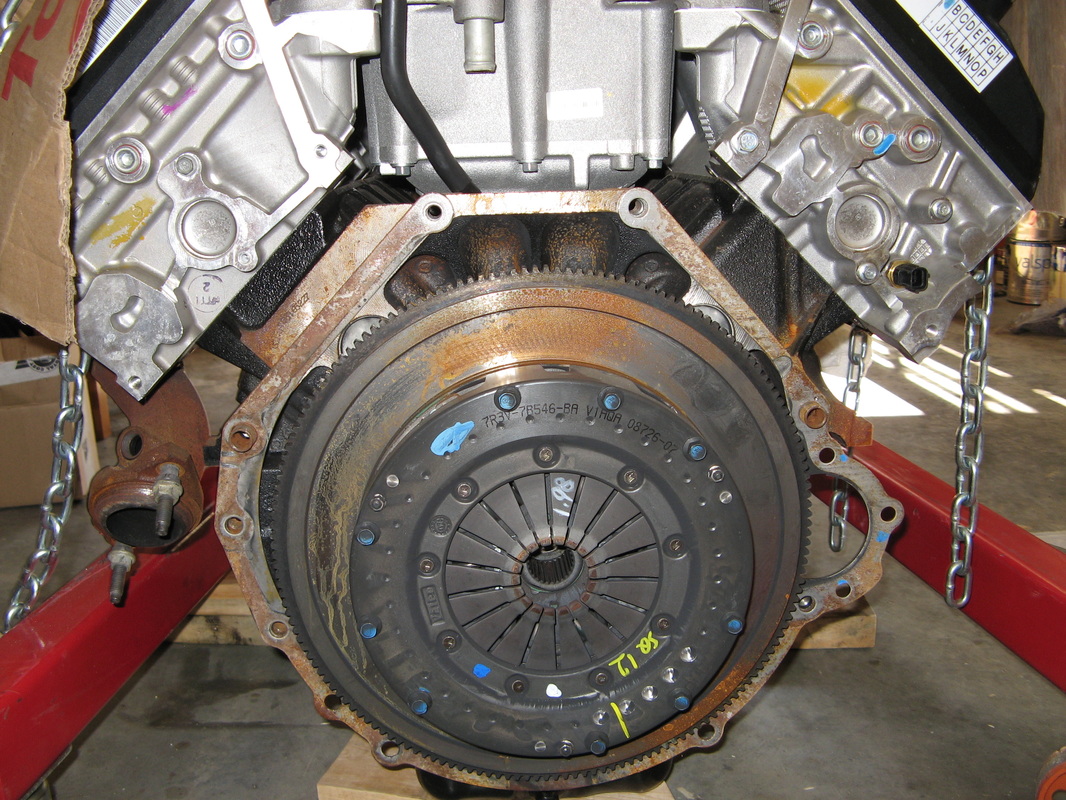
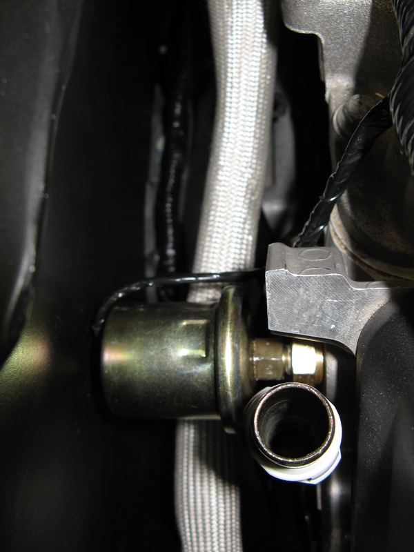
2.1 - Adding a Oil Pressure Sender
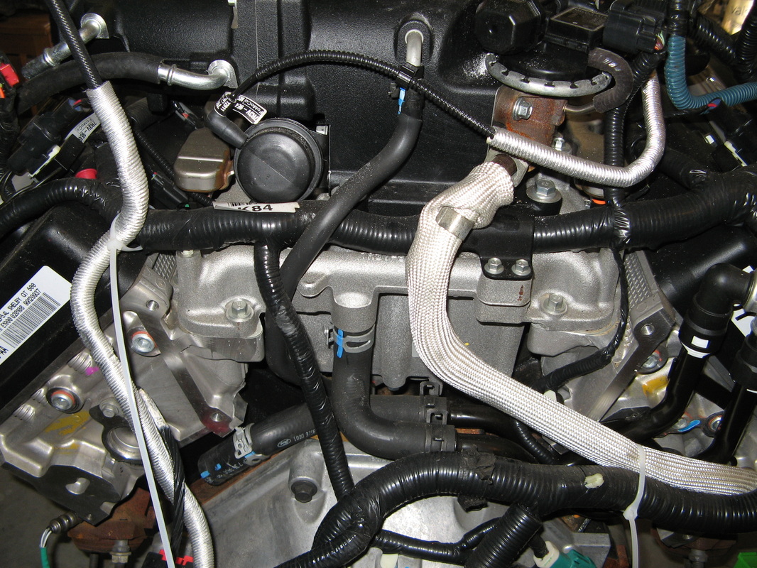
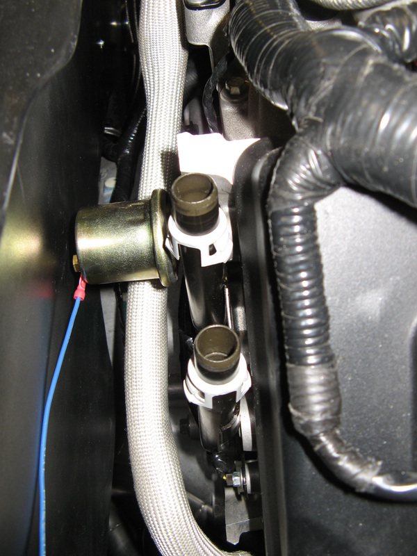
Now the stock GT500 engine has an Oil pressure switch right above the oil filter on the lower left-hand side of the engine. Well I wanted to add an oil pressure sender to match my gauges so I needed to find another spot to tap into the oiling circuit to get me a good reading. After looking over the engine a bit, there is an oil passageway plug on the rear of the right-hand head. This actually feeds the CAMS with oil, so it's as goog of a place as any. The first picture shows the rear of the engine. If you look on the right-hand side just to the left of the water pipes you will see a 1/2" NPT plug (or around that size). The second picture shows it a bit better, it's the top plug on the right side. Pull this out and add an adapter for the oil sender and presto, oil pressure. The third picture shows how this sticks out in the engine bay. The blue wire is removed later on, I was just checking it's length.
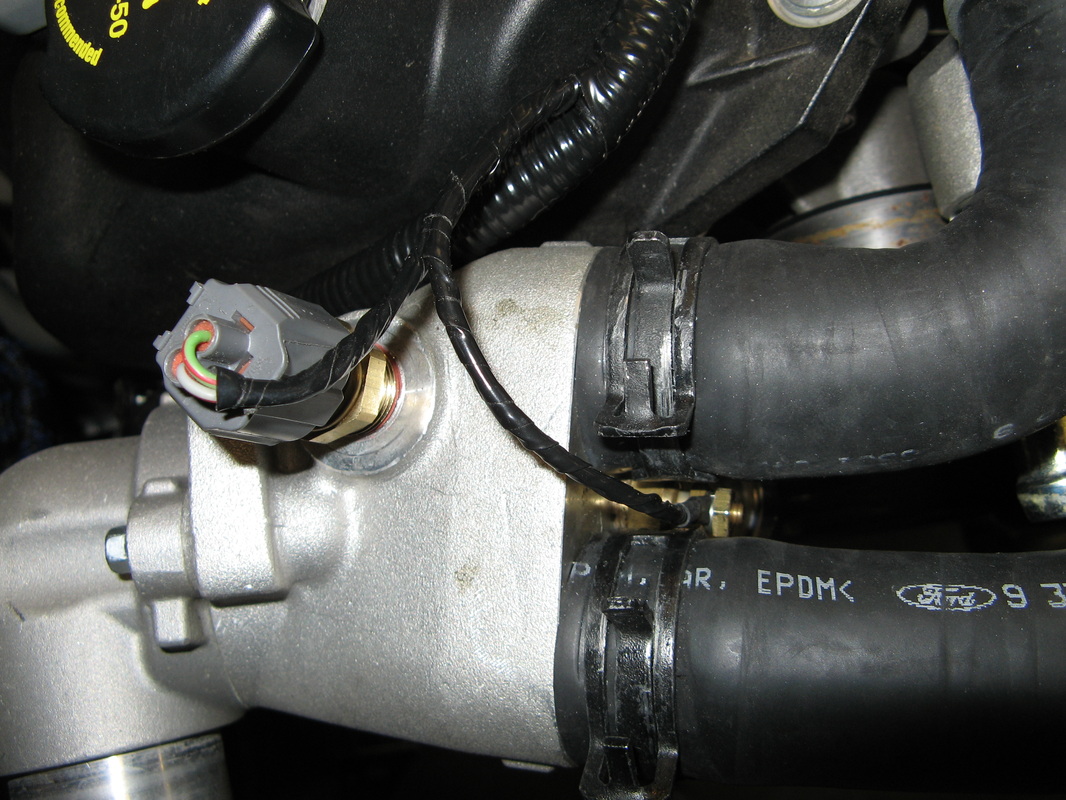
2.2 - Adding a second Temperature Sender
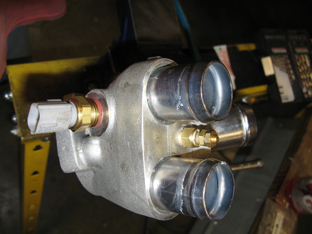
Since the ECU is going to use the primary temperature sender to run everything, we need to add a second one just for our gauges in the same area. This chunk is the thermostat housing on the front-right side of the motor. Here I drilled and tapped a NPT holes for my temp sender, nestled between the two water hoses for the head. This makes it very easy to high this sender and incorporate it into the main OEM harness.
2.3 - Incorporating the Sender Wires.
Here you can see how I'm going to route the sender wire for the oil and temperature senders in the OEM harness. Now this takes a bit of time, but once you get it all in there it looks so much better than having extra wires zip-tied on. Basically I'm trying to route everything to the main OEM inline-splice. That is the black connector between the green power distribution block and the two ECU connectors.
2.4 - Finishing out the Plug
Now to finish out the modifications to the OEM engine harness, I added a four-pin weather-pack connector to make it easy to hook up. The pinout for this connector is as follows:
1- Reverse Lamps Supply, Violet/White (VT-WH)
2- Reverse Lamps Return, Violet/Light Green (VT-LG)
3- Oil Sender (Yellow)
4- Temp Sender (Yellow)
Make sure you cap the unuses VT-WH and VT-LG wires that run to the ECU connectors.
1- Reverse Lamps Supply, Violet/White (VT-WH)
2- Reverse Lamps Return, Violet/Light Green (VT-LG)
3- Oil Sender (Yellow)
4- Temp Sender (Yellow)
Make sure you cap the unuses VT-WH and VT-LG wires that run to the ECU connectors.
2.5 - Final Engine Control Harness
Once you are all done, wrap it up nicely with some 3M super 33+ electrical tape to give it that OEM look. If everything is done right, then you shouldn't have any issues getting that engine fired up and running gauges. Here are a few pictures of the completed harness, and the connectors that we moved around.
3 - Reworking the Engine Power Harness
Now that the control harness is out of the way, we can turn our attention to the Power harness. Here you can see this stiff monster, that connects not only the engine to the battery but also the OEM power distribution box. Now since we have a smaller power distributiion box that connects directly to the battery, we can get right of a good portions of this beast.
3.1 - Slimmed down Power Cable
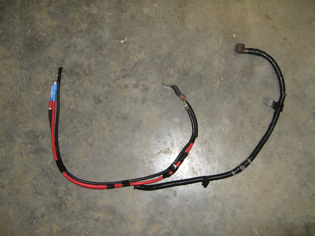
So after you get right of all the extra stuff the important wires are these:
1- Starter Power
2- Engine Ground
3- Alternator power with Fusible Link
I had some extra Moroso connectors so I was able to shove both +12V leads into a single connector. Now all you have to do is cover them up with some of the original split tubing and make it look nice again.
1- Starter Power
2- Engine Ground
3- Alternator power with Fusible Link
I had some extra Moroso connectors so I was able to shove both +12V leads into a single connector. Now all you have to do is cover them up with some of the original split tubing and make it look nice again.
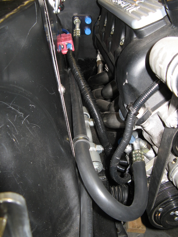
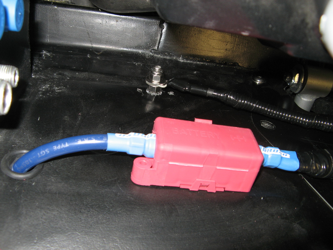
3.2 - Power Hookup
Since the engine is such a monster, I had no room for a battery up front. So I had to relocated it to the rear. I found this really nice battery relocation terminal from Summit Racing and bolted it to the inner fender. This gives me a nice solid mount for all my +12 battery needs in the engine bay. That and running a hefty 2-gauge wire from the battery makes everything just fat and happy. Here you can see how the main power cable comes out behind the AC compressor and then jumps to the inner fender panel for hookup.